# Reverse Engineering DevTerm Battery Module
**URL:** https://forum.clockworkpi.com/t/reverse-engineering-devterm-battery-module/7577
**Category:** DevTerm
**Tags:** tinkering, help, hardware
**Created:** [December 7, 2021, 7:25pm UTC](https://forum.clockworkpi.com/t/reverse-engineering-devterm-battery-module/7577 "2021-12-07T19:25:52Z")
**Posts on this page:** 13
**Page:** 1
### Author:  [@SpicyRamenCo](https://forum.clockworkpi.com/u/SpicyRamenCo)
#### Post date: [December 7, 2021, 7:25pm UTC](https://forum.clockworkpi.com/t/reverse-engineering-devterm-battery-module/7577/1 "2021-12-07T19:25:52Z")
Hello all,
I’m working on reverse engineering the battery module for a much larger project, currently my level of understanding with circuit design is very basic, learning as I make progress.
If anyone could graciously provide a high-res photo of the battery module, that would assist enormously. Particular focus on the 1812 footprint fuses would aid in identifying the design specifications for the protection circuit.
---
### Author:  [@Sebastian](https://forum.clockworkpi.com/u/Sebastian)
#### Post date: [December 7, 2021, 8:24pm UTC](https://forum.clockworkpi.com/t/reverse-engineering-devterm-battery-module/7577/2 "2021-12-07T20:24:01Z")
Did you find the schematic of the board on the Github?
---
### Author:  [@SpicyRamenCo](https://forum.clockworkpi.com/u/SpicyRamenCo)
#### Post date: [December 7, 2021, 8:38pm UTC](https://forum.clockworkpi.com/t/reverse-engineering-devterm-battery-module/7577/3 "2021-12-07T20:38:42Z")
Ive looked over the design schematic, my main focus on finding the operating parameters of the fuses is to identify the bidrectional protection requirements that power circuity on the main module requires.
Looking at the main modules power circuit is my next step, I want to make sure that my future main module prototype is backwards compatible.
---
### Author:  [@ghalfacree](https://forum.clockworkpi.com/u/ghalfacree)
#### Post date: [December 8, 2021, 11:08am UTC](https://forum.clockworkpi.com/t/reverse-engineering-devterm-battery-module/7577/4 "2021-12-08T11:08:14Z")
> [@SpicyRamenCo](#):
>
> If anyone could graciously provide a high-res photo of the battery module, that would assist enormously.
I only have a shot of the upper side, I’m afraid, but if it helps:

Looks like the forum has resized it: [here’s a 2000x1330 variant](https://gareth.halfacree.co.uk/pubimages/clockworkdevterm-batteryboard.jpg).
---
### Author:  [@SpicyRamenCo](https://forum.clockworkpi.com/u/SpicyRamenCo)
#### Post date: [December 8, 2021, 7:21pm UTC](https://forum.clockworkpi.com/t/reverse-engineering-devterm-battery-module/7577/5 "2021-12-08T19:21:32Z")
That was exactly what I was like looking for, thank you!
The board I’m developing will utilize a standard JST connection with a built in retention system for Lithium Ion battery packs (example image attached).

These battery packs generally implement built in protection, the concept is that two of these battery packs can be stacked.
The two areas of concern are fitting them within dimensional and thermal design constraints.
---
### Author:  [@SpicyRamenCo](https://forum.clockworkpi.com/u/SpicyRamenCo)
#### Post date: [December 8, 2021, 7:38pm UTC](https://forum.clockworkpi.com/t/reverse-engineering-devterm-battery-module/7577/6 "2021-12-08T19:38:00Z")
Additionally I mentioned main board development, while this is not currently my primary focus I did want to provide some conceptual information.
The main-board will utilize ARM architecture from an independent open source project called pine64.
You can take a look at their projects [here](https://www.pine64.org/), attached are photos of the SoEdge Baseboard and the SOPine Baseboard respectively.


---
### Author:  [@SpicyRamenCo](https://forum.clockworkpi.com/u/SpicyRamenCo)
#### Post date: [December 8, 2021, 11:15pm UTC](https://forum.clockworkpi.com/t/reverse-engineering-devterm-battery-module/7577/7 "2021-12-08T23:15:54Z")
> Update:
>
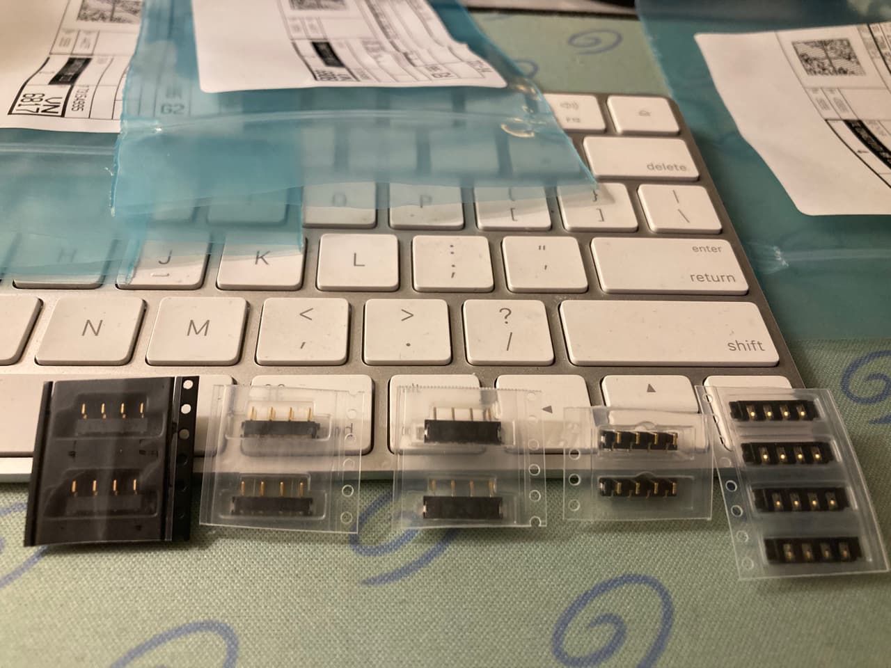
> Components identified and datasheets attached, additionally received board to board connector samples.
>
> DO-214AB-SMC: [MDD S5MC](https://drive.google.com/file/d/1KjEZiztULmJbP-oalwREtrHVq00jFQ2k/view?usp=sharing)
> ASMD1812SL: [JK-mSMD400l](https://drive.google.com/file/d/1GAh1MNheCAMJTb7YipUftA15Q6j0FWhL/view?usp=sharing)
Small request to the community; side profile images of male connector on battery module and measurements of connector placement.
In lieu of the later, I will reach out and see if I can get the CAD files for the board.

---
### Author:  [@DustinWoods](https://forum.clockworkpi.com/u/DustinWoods)
#### Post date: [December 11, 2021, 1:32am UTC](https://forum.clockworkpi.com/t/reverse-engineering-devterm-battery-module/7577/8 "2021-12-11T01:32:04Z")
> [@SpicyRamenCo](#):
>
> Additionally I mentioned main board development, while this is not currently my primary focus I did want to provide some conceptual information.
It sounds like you’re talking about designing a new main board to support the Pine64. Cool!
FYI, if you’re talking about using a pine64 module on the DT mainboard, they have different pin layouts and different form factor. Pine64 uses the 204 pin SODIMM layout, while the pi CM/A06/A04 uses the 200 pin layout.
> [@SpicyRamenCo](#):
>
> Small request to the community; side profile images of male connector on battery module and measurements of connector placement.
I’ve had luck getting measurements/DXF files from [help@clockworkpi.com](mailto:help@clockworkpi.com). If you need EXT board specs: [Designing a Ext. Prototyping Breakout (With Raspberry Pi Hat Compatibility) - #15 by DustinWoods](https://forum.clockworkpi.com/t/designing-a-ext-prototyping-breakout-with-raspberry-pi-hat-compatibility/6482/15)
---
### Author:  [@SpicyRamenCo](https://forum.clockworkpi.com/u/SpicyRamenCo)
#### Post date: [December 11, 2021, 5:28pm UTC](https://forum.clockworkpi.com/t/reverse-engineering-devterm-battery-module/7577/9 "2021-12-11T17:28:50Z")
I was hoping you’d jump in here and provide some input, love the work you have done on the EXT board!
In reference to the SOPine/SoEdge, I will be working on converting the board dimensions/layout to completely replace the DevTerms “main” board as a drop in replacement.
The design concept for the replacement battery board is complete, currently I’m at a stall due to several factors. First is the connector to the main board, the one that the DevTerm battery module uses is a thru-hole component and after hours of searching through digikey, mouser, and lcsc I have come up empty.
The second problem I’ve run into was dimensions, I will follow DustinWoods advice and reach out to clockwork support to see if they are willing to release them to the community.
Since I do not currently own a DevTerm I was hoping to have the bottom cover 3d printed, however the .obj file that’s provided on the github isn’t broken down into the various components and when the file is uploaded to online printing services, I’m getting a cost in excess of $600 for the print as-is.
My next task is to see if the layers can be separated in the provided model so the price can be brought down to a reasonable cost.
Schematic for the batt board is below, please remember that it is not dimensionally correct. The board cut-outs are so that a “velcro” strap is placed through the board to secure the battery, example shown below. I welcome any ideas, comments, or thoughts and if I’ve overlooked something stupidly simple/complex please feel free to put me through the ringer!


---
### Author:  [@ghalfacree](https://forum.clockworkpi.com/u/ghalfacree)
#### Post date: [December 12, 2021, 10:59am UTC](https://forum.clockworkpi.com/t/reverse-engineering-devterm-battery-module/7577/10 "2021-12-12T10:59:15Z")
> [@SpicyRamenCo](#):
>
> Since I do not currently own a DevTerm I was hoping to have the bottom cover 3d printed, however the .obj file that’s provided on the github isn’t broken down into the various components and when the file is uploaded to online printing services, I’m getting a cost in excess of $600 for the print as-is.
>
> My next task is to see if the layers can be separated in the provided model so the price can be brought down to a reasonable cost.
It’s already separate objects - just in a single OBJ file. The object you need, the back panel, is labelled “object\_82”. [There’s more here, including a link to an OBJ file with just the back panel](https://forum.clockworkpi.com/t/print-files-for-devterm-chassis/7617/2).
---
### Author:  [@DustinWoods](https://forum.clockworkpi.com/u/DustinWoods)
#### Post date: [December 13, 2021, 12:57am UTC](https://forum.clockworkpi.com/t/reverse-engineering-devterm-battery-module/7577/11 "2021-12-13T00:57:49Z")
You should be able to have just one battery connector (U1/U2) for a single battery and reduce the components to one diode and one fuse.
**Some thoughts on using non-18650 batteries:**
Might work fine without re-programming the power management ic. But if you need to reprogram it, you can communicate with it using GPIO0 and GPIO1. (TWSI/IRQ)
> **[116.AXP228\_V1.1\_20130106.pdf](https://wiki.friendlyarm.com/wiki/images/5/5e/116.AXP228_V1.1_20130106.pdf)**
>
> 1906.11 KB
I’m not a battery expert, but I think it should be fine as long as charge voltages are the same. (It does make me wonder what programming CPi has done with the power management chip)
That connector is very strange indeed! The only thing I could find is that _it might_ be called a “card edge connector”. In the schematics for the main board the part (female side) is listed as CF200-00204-1G1. But I could not find it anywhere either. Once you get a DevTerm in hand, you might be able to figure out something creative. Like maybe a right-angle header would do the job.
The holes for velcro straps is a nice touch! And ya know, with this design and a JST connector, you could use just about any shape battery.
I’m looking forward to seeing more of this!
EDIT: One other thought, make sure to make big fat copper traces for the power! You might be already good, but with all that board space it might not hurt to make them bigger(?) If you’re not sure there are tools online for estimating copper trace sizes based on Amp ratings.
---
### Author:  [@SpicyRamenCo](https://forum.clockworkpi.com/u/SpicyRamenCo)
#### Post date: [December 13, 2021, 8:00pm UTC](https://forum.clockworkpi.com/t/reverse-engineering-devterm-battery-module/7577/12 "2021-12-13T20:00:07Z")
Very informative comments as always, I greatly appreciate your input, thank you for providing the datasheet for the AXP288.
Based on my prior research it is fairly difficult to obtain the AXP288 outside of a commercial vendor, it seems like a wonderful PMIC for this application.
One of main reason I plan on re-designing a SOPine/SoEdge baseboard for this application is due to the commitment of the vendor to provide long term support for the Allwinner R18(10 years).
I second the idea of omitting U2 and going with one battery on the next revision, as there are JST batteries out there push over 4500mah+.
TE Connectivity has some wonderful SMD connectors which I have in hand, my main concern is putting too much stress on them and having them break off.
Thank you for looking into the connectors, as feared they seem to be obscure, but wonderfully implemented.
If anyone desires to implement more power functionality, I welcome ideas/thoughts/wishes for the next revision!
---
### Author:  [@mmirate](https://forum.clockworkpi.com/u/mmirate)
#### Post date: [December 28, 2021, 9:41pm UTC](https://forum.clockworkpi.com/t/reverse-engineering-devterm-battery-module/7577/13 "2021-12-28T21:41:07Z")
> [@SpicyRamenCo](#):
>
> ideas/thoughts/wishes for the next revision!
A PMIC for the LiFePO4 chemistry. It has much better longevity (and safety), but it has a different voltage range - minimum discharge of ~2.5V and max charge of 3.6V.