I use a small DS3231. It’s very small and works great.

2 Likes
Same here. I also soldered the wires directly onto the Pico. It works perfectly.

Apparently the battery was dead (0.9v). Made it so I never have to worry about RTC batteries again.

Ideally I should’ve gotten battery power from C102 near the AXP chip, but that looked risky…

Also: if anyone has problems with their keyboard not showing up after the mod, check picocalc_keyboard.ino: wait a bit before initializing i2c by prokrypt · Pull Request #18 · clockworkpi/PicoCalc · GitHub and try the keyboard firmware I compiled.
4 Likes
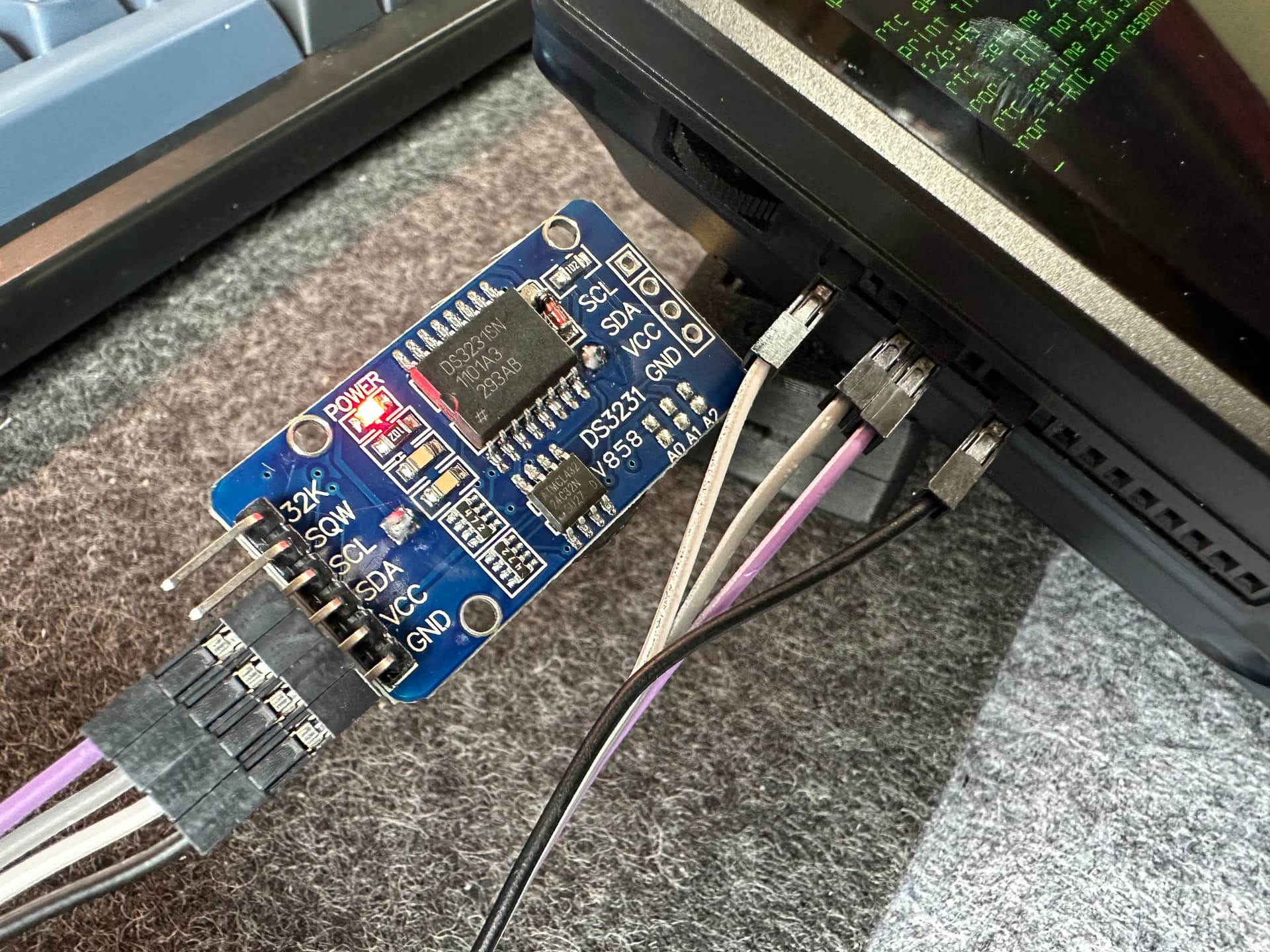
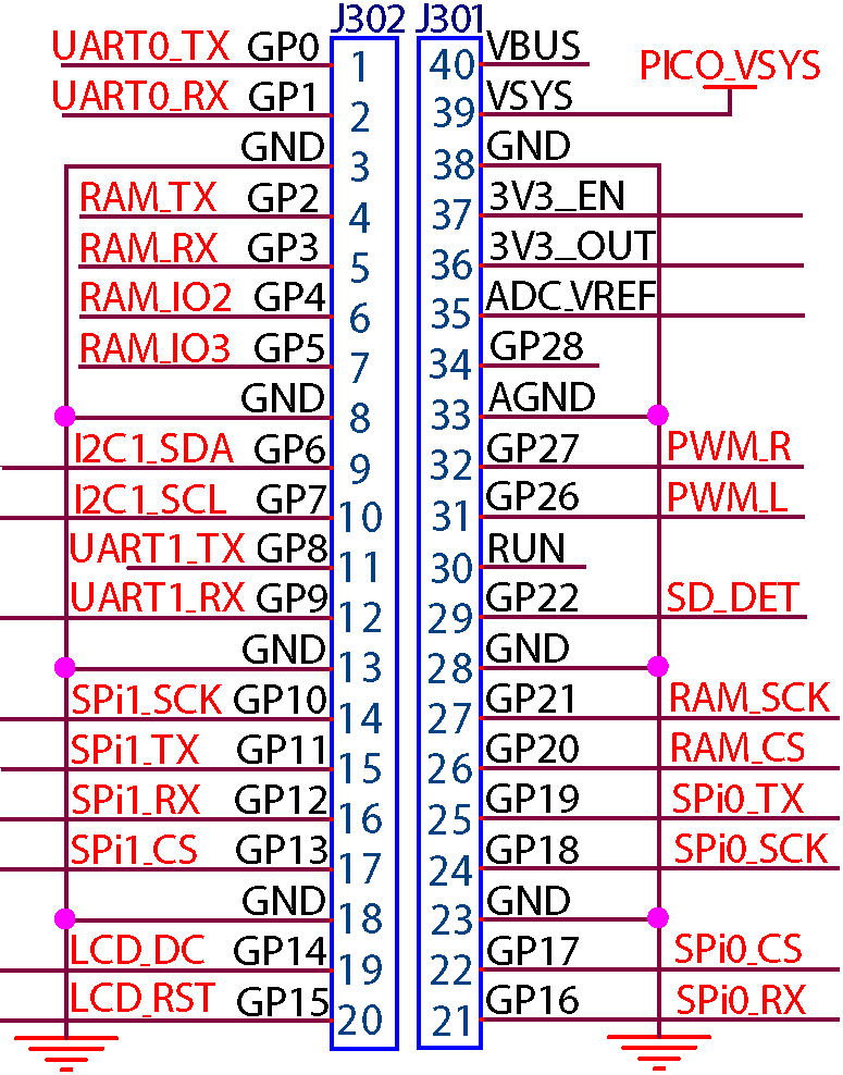
I got a DS3231SN module and before I solder it internally I thought I test it outside my PicoCalc and connect it to the Pico’s corresponding I2C ports that are available on the left side – according to the Pico Pi 1’s pin diagram here.
So I connected SDA to pin #4 (counting from the top, GP4), SCL to pin#5 (GP5), GND to pin #8 (GND) and VCC (is it really necessary?) to pin #1 (3V3).
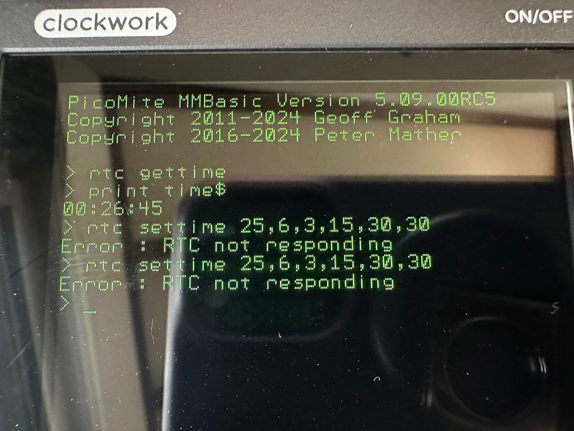
However, when I try to …
rtc settime 25,6,3,15,30,30
… I get an Error : RTC not responding from MMBasic.
Any ideas/hints/tips? ![]()
![]()
Not sure if that will make a difference but i would start by updating mmbasic to v 6.02rc25
Okay, did that (on the original Raspi Pico 1), worked, on 6.00.02RC25 now.
Still the same problem/error. ![]()
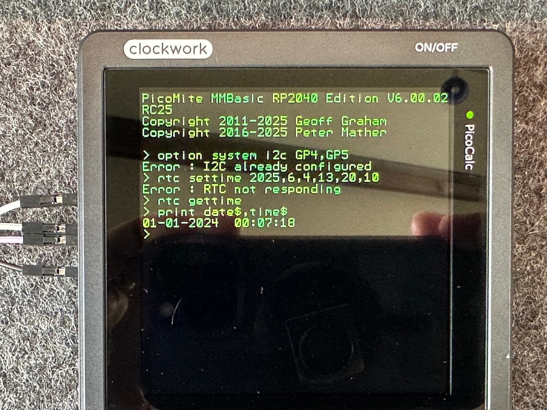
This is with all 4 pins connected, even 3V3. Still not sure if it’s good to connect this because the module has its own power supply (CR2023 Lithium cell) and I hope the module doesn’t try to charge this Lithium battery!?!
I see that when you tried to set the I2C pins, they were already configured. Did you check the OPTION LIST to make sure that they are set to GP4 & GP5? If not, your GET TIME would be going to the wrong pins, and the PicoCalc would never see the RTC.
1 Like
Ah-HAA! OPTION LIST says:
...
OPTION SYSTEM I2C GP6,GP7, SLOW
...
So there we have the reason why it’s not working! Thank you, @granzeier!
Now, unfortunately, GP6 and GP7 are not available from the outside of the PicoCalc. ![]() How can I make MMBasic to use GP4 and GP5 (which are not listed by
How can I make MMBasic to use GP4 and GP5 (which are not listed by OPTION LIST so I guess they’re free)? Obviously, OPTION SYSTEM I2C GP4,GP5 didn’t work as we can see in my last photo.
GP4 and GP5 seem to be the default I2C pins of the Raspberry Pi Pico. I’m a bit surprised that those were changed to GP6 and GP7 in MMBasic.
Edit: wrong language (german)
Please see my post from April 9th. I had the same problem. But in the options list, you can see that GP6 and 7 are already being used for other purposes.
I then soldered the clock directly to the Pico. It works perfectly. I can also send a photo if you’d like. Otherwise, just ask again.
Regards,
Herbert
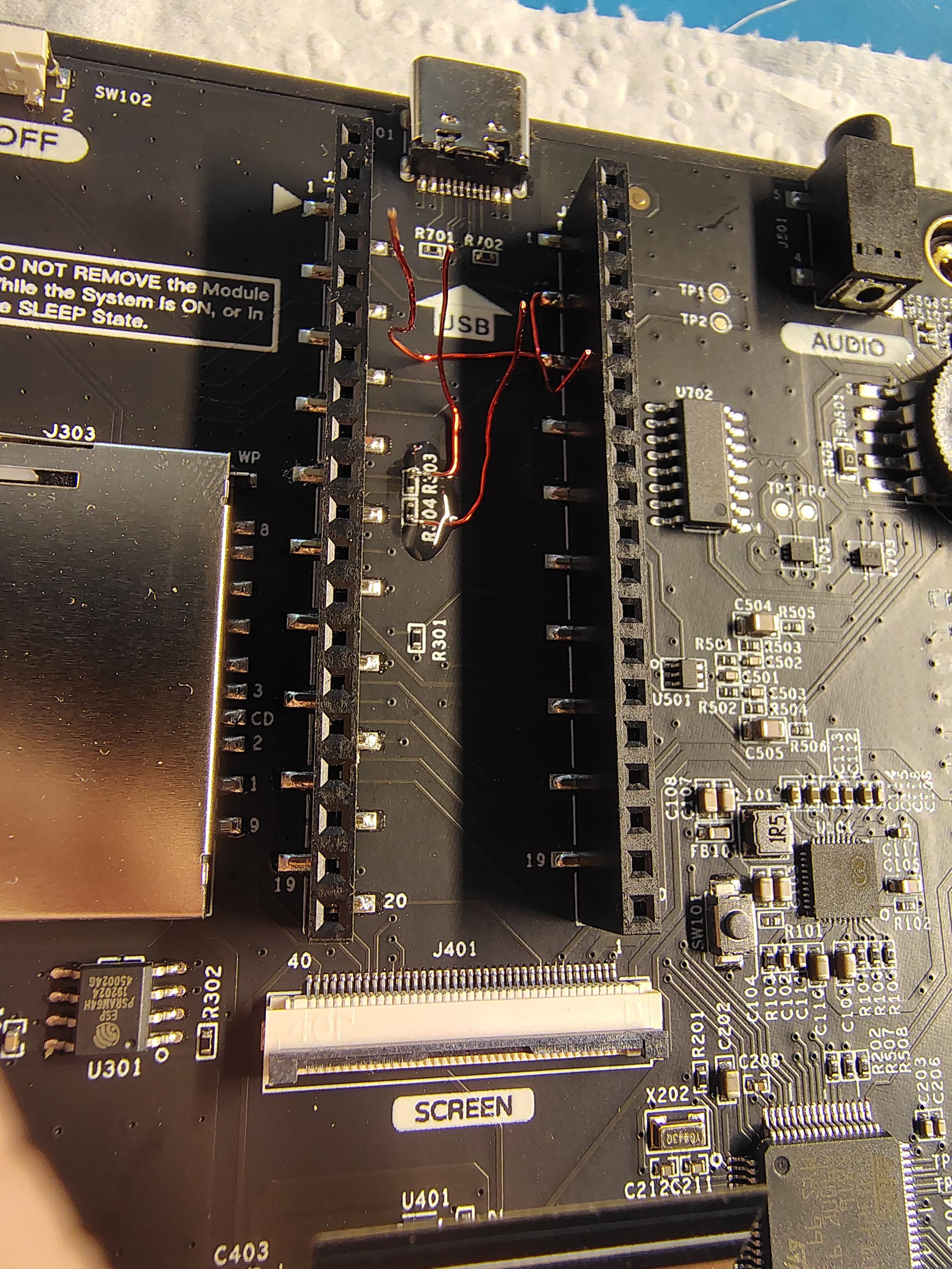
Yes if VERY carefull with a fine tipped soldering iron you can connect internally like this…

NOTE the supplied socket pinout is REVERSED in the PicoCalc docs. I’ve corrected as below and you can see the above image he has connected to gp6 and gp7. He’s used the ‘3.3V out’ pin for power yet many RTC modules will take higher too (5V). Ill be considering wiring directly to the main batteries 4.07v (or maybe the switched 4.04v ‘vsys’ pin , measured just now) so as not to load the 3.3V regulator when adding even more modules…
UPDATE - The tiny onboard power distribution mosfet switch (4603 u102) is set to current limit VSYS from the batteries at 2A (6.8k/3.4k@1%) yet has no heatsink other than the pcb copper area. No idea how much headroom is left. I’m now thinking of a second mosfet switch triggered by this one for future module power beyond the initial RTC…
HARDWARE MOD ADVICE GIVEN IS TAKEN AT YOUR OWN RISK.
Yes, @Herbert, GP6 and GP7 – as I wrote – are already used for I2C. This can be seen in my photo.
I want to use GP4 and GP5 for I2C instead.
However, OPTION SYSTEM I2C GP4,GP5 doesn’t work, gives the error Error : I2C already configured. – which we knew already.
The question is: How can I2C be configured to use GP4 and GP5 instead?
GP4 and GP5 don’t seem to be used already. I don’t see them being mentioned in the output of OPTION LIST:
PicoMite MMBasic RP2040 Edition V6.00.02 RC25
OPTION SERIAL CONSOLE COM1,GP0,GP1
OPTION SYSTEM SPI GP10,GP11,GP12
OPTION SYSTEM I2C GP6,GP7, SLOW
OPTION COLOURCODE ON
OPTION DEFAULT COLOURS GREEN, BLACK
OPTION KEYBOARD I2C
OPTION CPUSPEED (KHz) 200000
OPTION LCDPANEL CONSOLE ,, FF00
OPTION DISPLAY 26,40
OPTION LCDPANEL ILI9488P, PORTRAIT,GP14,GP15,GP13,,INVERT
OPTTON SDCARD GP17, GP18, GP19, GP16
OPTION AUDIO GP26,GP27', ON PWM CHANNEL 5
OPTION PLATFORM PicoCalc
(I removed line breaks; and, yes, the one single ’ character after GP27 in the AUDIO line option is indeed there.)
So I see these GPs in this list: GP0, GP1, GP10, GP11, GP12, GP6, GP7, GP14, GP15, GP13, GP17, GP18, GP19, GP16, GP26, GP27 – but not GP4 and not GP5. ![]()
So what you are saying is that MMBasic is using GP6 and GP7 for I2C is not changeable by the user?
What’s the OPTION SYSTEM I2C SDApin, SCLpin then used for? ![]()
Already in use for the onboard keyboard/backlight STM32 controller. Hence can’t be changed. Note MMBasic (PicoMite) was not written for the PicoCalc !
NOTE re your previous comment !. RTC modules are sometimes designed to take rechargeable batteries. Do your research on the module and what battery type it expects. Some have a link that must he broken if a non-rechargeable lithium battery is inserted !.
How about OPTION I2C2? Could you use the second I2C channel for the clock?
can’t you just connect it to the same I2C bus as the keyboard, as long as there are no address conflicts that should work
Using a custom firmware, it’s possible to use the RTC inside the stm32/keyboard with only the 18650 to keep RTC running (tested this feature the last week).
I didn’t want to mess things up with rough soldering and batteries everywhere…
(…so I messed up the code instead :3)
But yes, you have to manage the AXP power supply differently and code all the interfaces from the stm32 to the pico this way.
3 Likes
Hi Jack, I read that the register mapping is not necessarily identical from the factory stm32 firmware. What about starting in compatibility mode, and have a special register to switch to the new mapping, so that the firmware is compatible by default?
This is a bit off topic, I was mainly pointing out the possibility of using the STM32’s existing RTC (rather than adding a new one).
I must admit, It’s quite sad to see the STM32 being used so poorly (in term of power management and the availables features).
But to respond to the remark: it’s a good practive if we can avoid basing compatibility on the low level, but I’m not yet sure what the registers will look like in the end.
Reviewing memory allocation will be necessary, but changing the addresses is probably not necessary. We’ll have to see.
The STM32 running the keyboard has an RTC, but no one is using it?