The Pico cores have two i2C buses (known as i2C/i2C2 in MMBasic or i2C0/i2C1 by Raspberry). They can be clocked at different frequencies yet it appears the one connected to the keyboard/backlight STM32 causes errors at 100Khz so limited to a measly 10Khz.
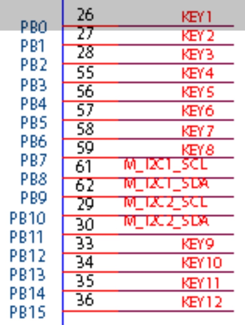
It seems i2C/i2C0 is handling the STM32 yet the sloppy schematic appears to show BOTH i2C channels connected to the STM32. Different labels on the STM32 and Pico socket add to the confusion.
Anyone with actual electronic/C programming experience of PicoCalc i2C confirm what the two i2C channels ‘actually’ connect to and if the second (i2C2/i2C1) channel can be run at higher clock than 10Khz ??. A list of i2C connections and used addresses would be the icing on the cake….
The schematic can’t possibly show both I2C buses being connected, because only one I2C pair is configured as such on the pico connector. Every other pin is configured as non-i2c peripherals (UART, SPI, PWM or generic GPIO.)
There’s at least 5 different pairs of pins that can be re-configured to go to a particular I2C bus, as shown on the official Pico pinout diagram. It’s up to you to decide which ones are the most appropriate.
Implying 2 channels unless these are the STM32’s own ??. If so where does the Pico i2C2 connect ?. We need a pcb layout to trace the tracks. A past nosy into the Picomite build C files seemed to imply the first channel was used for STM32/keyboard, not second. I’ll look again but hate C.
Yes obviously other pins could be allocated to the first i2C channel if not used yet that seems to only give the possibility of the ram chip lines. I’ve often thought of removing that damn chip if 10Khz isn’t enough.…. Oh for a PicoCalc2 with better i/o.
Why are you looking at the STM32 when you’re concerned about the Pico?
The STM32 has 2 I2C buses, one goes to the Pico, and the other goes to the PMIC.
All the labels on the STM32 are for the STM32, and all the labels on the Pico are for the Pico. There’s net-ties elsewhere on the schematic that links any two signals that need it.
Trying to see how the busses are used, where they connect. One issue is the MMBasic RTC commands rely on the ‘system i2c’ option so may need to connect further modules to the first i2c channel instead for higher speed. Yes I could move the lot to the first and set the system clock myself from the rtc….
As I previously said, you can’t talk at 100 kHz when the slave is programmed to handle 10 kHz.
So, in order to use the 100 kHz on the STM32<=>PICO I2C line, you should firstly flash a modified version of the STM32 firmware using 100 kHz as I2C clock, and use 100 kHz on your pico in a second time.
NB: You can also make a register on the stm32 you can use to dynamically change the I2C frequency on the stm32 side.
It would be great for someone to test higher speeds but yes will need to be changed both on the STM32 and core Picomite build (thoughts @adcockm ?). Wonder why they chose such a snails pace 10Khz ?, I suspect they hit issues, bad track crosstalk or such. Unmodified Picomite starts at 100Khz, and called ‘slow’ lol. Some devices I’m playing with go to 1000Khz and beyond. Lower speed lowers power draw and allows for longer untwisted/screened Stemna/Qt cables but restricts storage speed, audio/signal sampling etc…
‘Both’, two controllers talking to each other hence clocks must match, on the other hand standard i2C modules handle a range of clocks. ‘Change’ as this is far below the minimum normally used for i2C and severely limits i2C storage speed, high speed sampling etc. An FRAM chip I’m playing with at the moment will run at 1000Khz and still only draw 200uA .
@adcockm who has done some great Picomite builds for the picocalc cores, accidentally set 100Khz in one and it caused issues so reduced it to the 10Khz as used in the original ClockworkPi PicoMite build included with the PicoCalc….
I think I am wasting my time here, good luck with your problem.
I suggest you read the documentation, pay attention how the bus is clocked and how the bus can be slowed down with clock stretching.
According to the MMBasic documentation the command OPTION SYSTEM I2C the speed can be set to SLOW (100KHz) or FAST (400KHz).
This option using WebMite Ver 6.00.03 on a Pico 2W is set to SLOW.
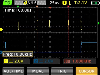
With the help of a plumbing modification (3 mm rubber washers) to keep the board in place without the back cover I was able to connect a ZOYI ZT-703S oscilloscope multimeter to I2C1 SDA (GP6) and I2C1 SCL (GP7). The following screenshot confirms that the I2C1 clock speed is 10KHz.
Unfortunately I was unable to find this in the documentation.
Digging into the forum and the source code I was able to find why this is has been done. However, while looking at the source code I noticed a few things that I may look into at a later date when I have time available because it should be viable to run at 100 Khz or more. (I have successfully tested I2C at 4MHz (and more) using wirewrap between multiple Pico 1).
One issue I noticed in the code is that every Pico I2C interface is clocked at 10KHz, this does not make sense if this was done because of a communication problem using I2C1 with the keyboard.
Don’t expect anything in the mmbasic codebase to make sense. It’s not written with any sort of deep skill or introspection, just sheer bloodyminded stubbornness.
Also the PicoCalc port is mostly a fight against the various issues from the upstream codebase. Both channels were clearly hardcoded to 10kHz during initial bringup and it was forgotten to reset the one that doesn’t go to the keyboard afterwards.
Finally, the 10kHz limit has nothing to do with the hardware, and is entirely a workaround for issues with the keyboard firmware, which has a naive i2c slave implementation. A better one would have no problems running at whatever speed the bus is at.
Yeah F1 series of STM32 is a really old design, but it should have the clock stretching mode.
In any case, you need to dev a custom firmware to enable it. I suppose CWPi doesn’t want to take too much time on the STM32 dev.
I still can’t figure out why 10 kHz have been choosen. Probably a chicken-egg choise at the end.
EDIT: I just read again I2C driver init, normally the sketching is on by default, but probably need to set the max frequency first. I’ll try with 100 kHz…
Great! It’s work! (partially… glitchs occurs due to the software handling)
So just need to set the “max” frequency, on the STM32, you want to use for your bus.
They just produce then leave further dev/fixes to you guys. Shame they couldn’t get it right out of the barn.
I’m living with 10Khz at the moment but as I add more devices I’m no doubt going to find issues soon. If a fix isn’t found the PSram is coming out (to keep things clean) and I’ll use the first i2C channel, pushing it as far as it’ll go via PicoMite.
Yes, in theory, it’s a bonus to have the firmware out-of-the-box xD
I just noticed more glitch in the handler of the I2C slave at 100 kHz. Signals are clear on scope…
Definitely the slave code is garbage!
I didn’t updated it as this will break compatibility with picomite. But… keeping garbage because we’re already in garbage sound stupid too.
So I didn’t recommend moving to 100 kHz without a proper review/handling of this part in the firmware.
Using the master clock in 10 kHz still work.
EDIT: From what I see on test program, the I2C crash occur when writting data. I’m become more and more certain about the slaver driver implementation.