Here we go! I got my prototyping board about 3 months ago from @DustinWoods (thanks mate!!) and only just got my Devterm 3 days ago; and built it last night.
The day the two meet has finally arrived!
This is showing the relative size of the stock expansion module vs the custom proto board. The main thing I would be missing, and want to add to a future revision is a fan.
This is a closer look at the protoboard. Notice the ribbon cable folded PERFECTLY - yup that was @DustinWoods ’s handy work. Nice!
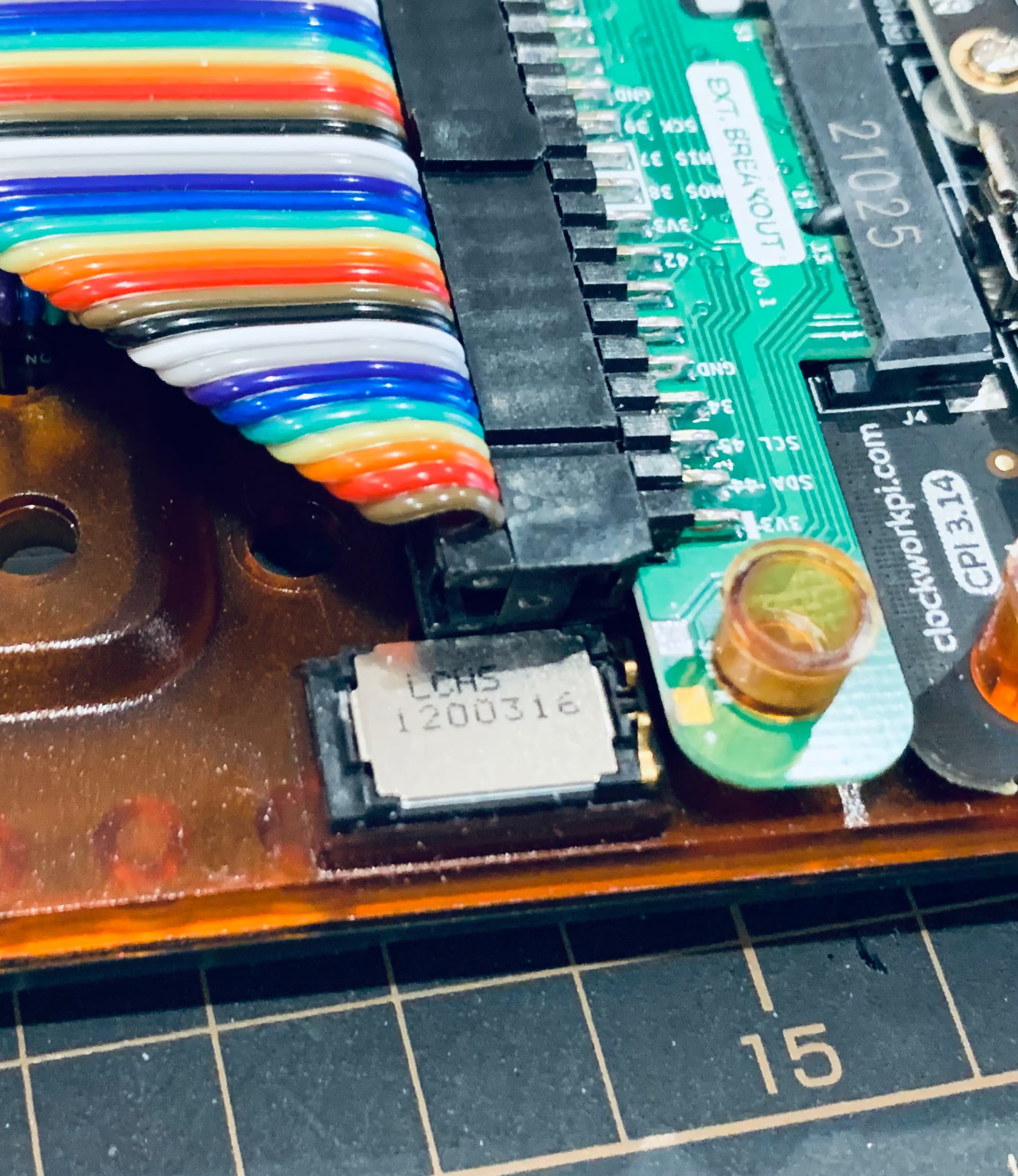
Having not seen a unit on hand, I’m sure @DustinWoods was making some educated guesses re fit. All of the stand-off pegs fit perfect! However the pogo pins of the audio module are off just by a fraction! It’s also only the right speaker, so a future module containing both left and right would be great! For now I’ll either a) live with mono or b) find the pins that correlate to the left channel.
Next module, the hole is slightly too wide, having the bracing peg fall right through. Not really a problem in my opinion, since it doesn’t need to be pinned down; just aligned to prevent rattling. It will however mean the bracing post will be down 1-2mm more than it should, possibly affecting the chassis structural integrity. Nothing you can’t fix with a small 3mm ID washer.
Here it is installed. The posts line up perfectly! There are additional posts that are + shaped. Perhaps having the PCB matching the shape would be good for stability. The printer module does this, and isn’t pinned down. Currently it’s an open circle. But as above, it doesn’t really matter.
Ribbon cable installed! There’s some small clearance problems with the right speaker, but only just. It can snuggle wiggle it’s way in. But it wouldn’t hurt to move it up a couple of millimetres.
Let’s see it all together. Just look at that perfectly placed ribbon cable. Divine!
We will have a slight void on the right edge of the devterm, since we aren’t provided with any backing plates. Not a problem tbh. Just get some pla plate, an ice cream container, or heck; electrical tape, and cover it up if it’s a problem. Oh and there are no fitting issues. I just didn’t fix it down, since I don’t like putting undue stress on things unless I really need to; especially plastic!
(Whoops, I put the wrong plate on. Eh, you get what I mean. :))
The main thing I would like to see in a revision would be:
-
An integrated fan, similar to the stock board. An even bigger one could even be possible, since a lot of the printer circuit wouldn’t be needed.
-
A second pogo pad for the left speaker. Even just a small 10mm x 12mm board to go over the offset peg with a jumper lead leading to the breakout board would be fine.
-
UART pass through for any debug/diagnostics, especially if you’re prototyping.
-
Moving the left speaker pads 1-2 mm to the left to align better.
-
Move the ribbon connector up 1-2mm to give more clearance to the right speaker. (Or dremel the headed down)
-
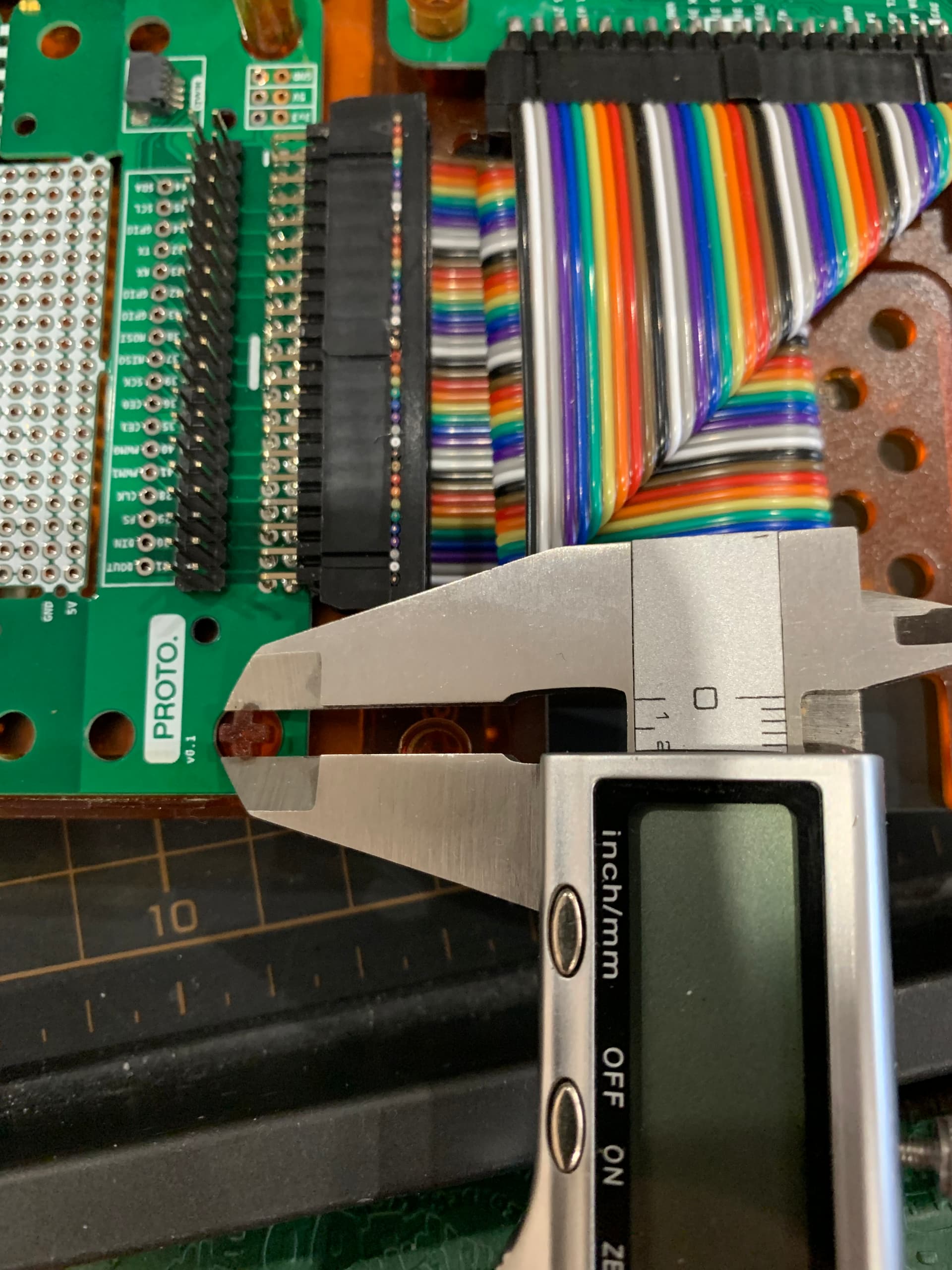
Decrease the diameter of the second board’s mounting holes to match the post, and not the plug. (A rough Vermeer caliper measurement is just shy of 5mm for the post)
-
Change the second row of mounting holes to + shaped slots, to reduce play and increase stability.
Hopefully this gives you all some insight about the potential that the expansion slot has. If anyone else has one, post up pics and any insight! I’d love to see @DustinWoods do a revised version!
Edit: Whoops! Reverse every mention of left/right speakers - I forgot I was working on this upside down!
Also oops a lot of the things I suggested have already been mentioned as a revision! I didn’t read all the posts first!