Oh sure you do as you want, I’m not going to call the police because you are connecting your fan directly to 5V!
As for the rest, that’s your devterm, you do whatever you want with it, though I would recommend not to try to crush, shred or blend it, it would be a bit sad
This is all great work - very happy to see people are already getting started on this front. It was my intent to design some custom boards for this as well.
One thing of note, I see some mention of cost of PCBs. I’m currently working on a project where this is a concern as well, and we have opted to go with boards which are 100x100 mm or smaller because we can have them made by SeeedStudio for ~$5 for 10 boards (2 layer). Any increase over the 100x100 or switching to 4 layer will of course increase the price (roughly 10x), but neither of those looks like a concern here. You of course have to keep shipping (from HK - will cost more than the $5 for boards) and turn around time in mind (about 5 days to make, generally the same or a little longer to ship). If you have multiple designs in mind, you can submit them at the same time to keep the per unit shipping cost down.
Again, great work and looking forward to when I can start working on some of my own mods!
This is awesome - the thing is not even out and there are already mods for it. I might be interested in one of these breakouts once I decided which model I wanna get. At this point I just wanna buy one to be part of the community
Happy July! I think we’re all feeling the anticipation of another announcement.
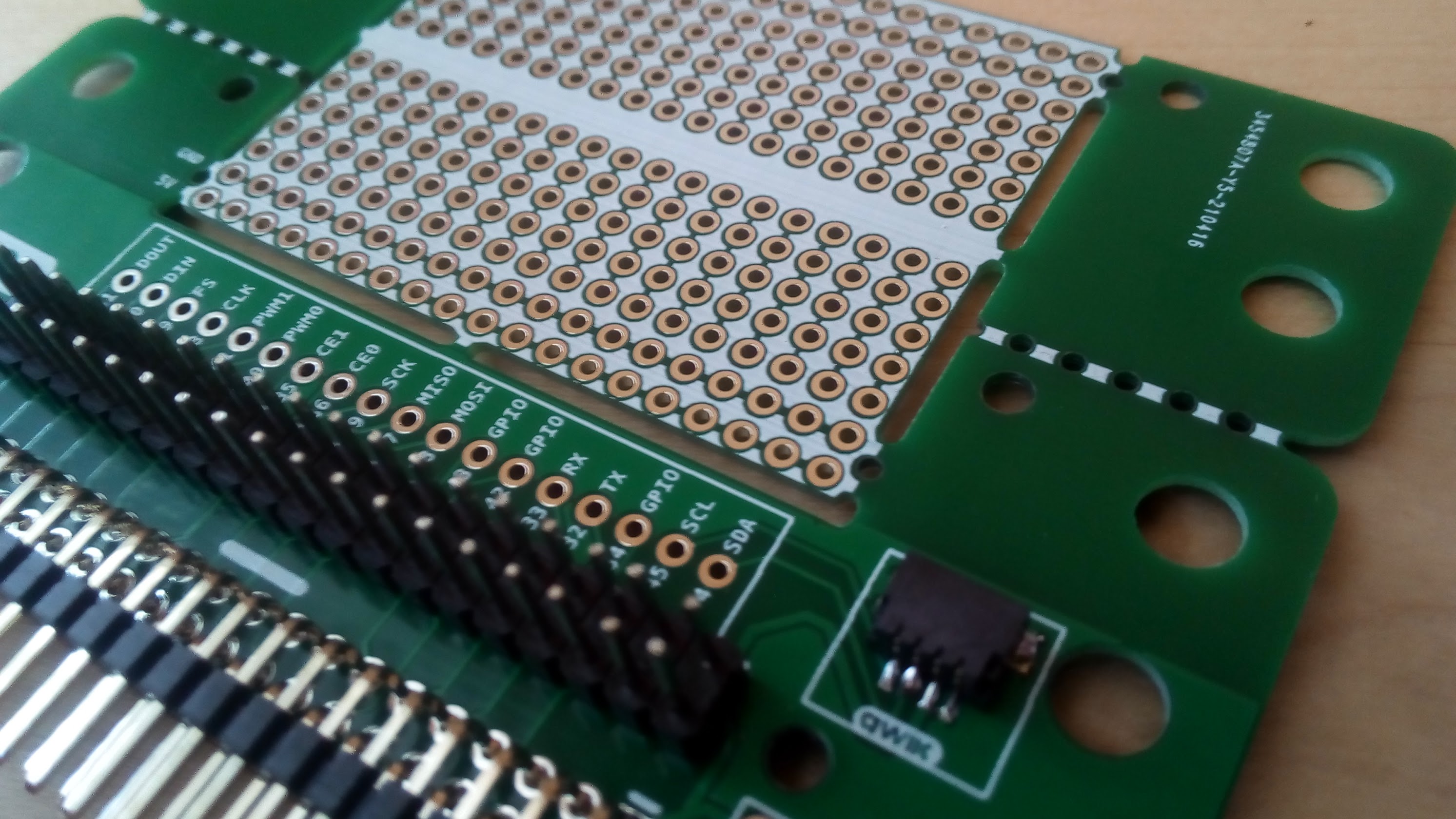
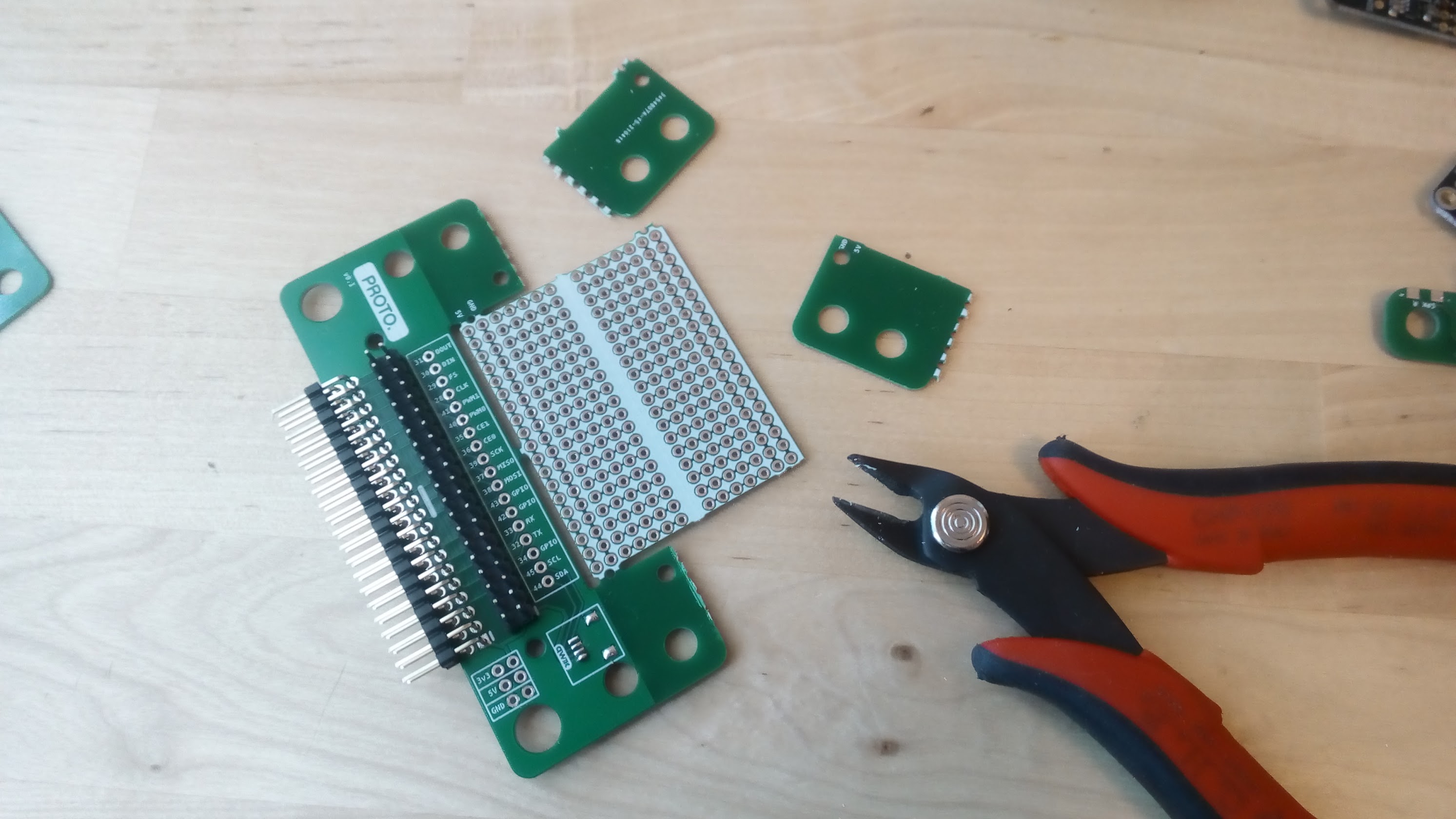
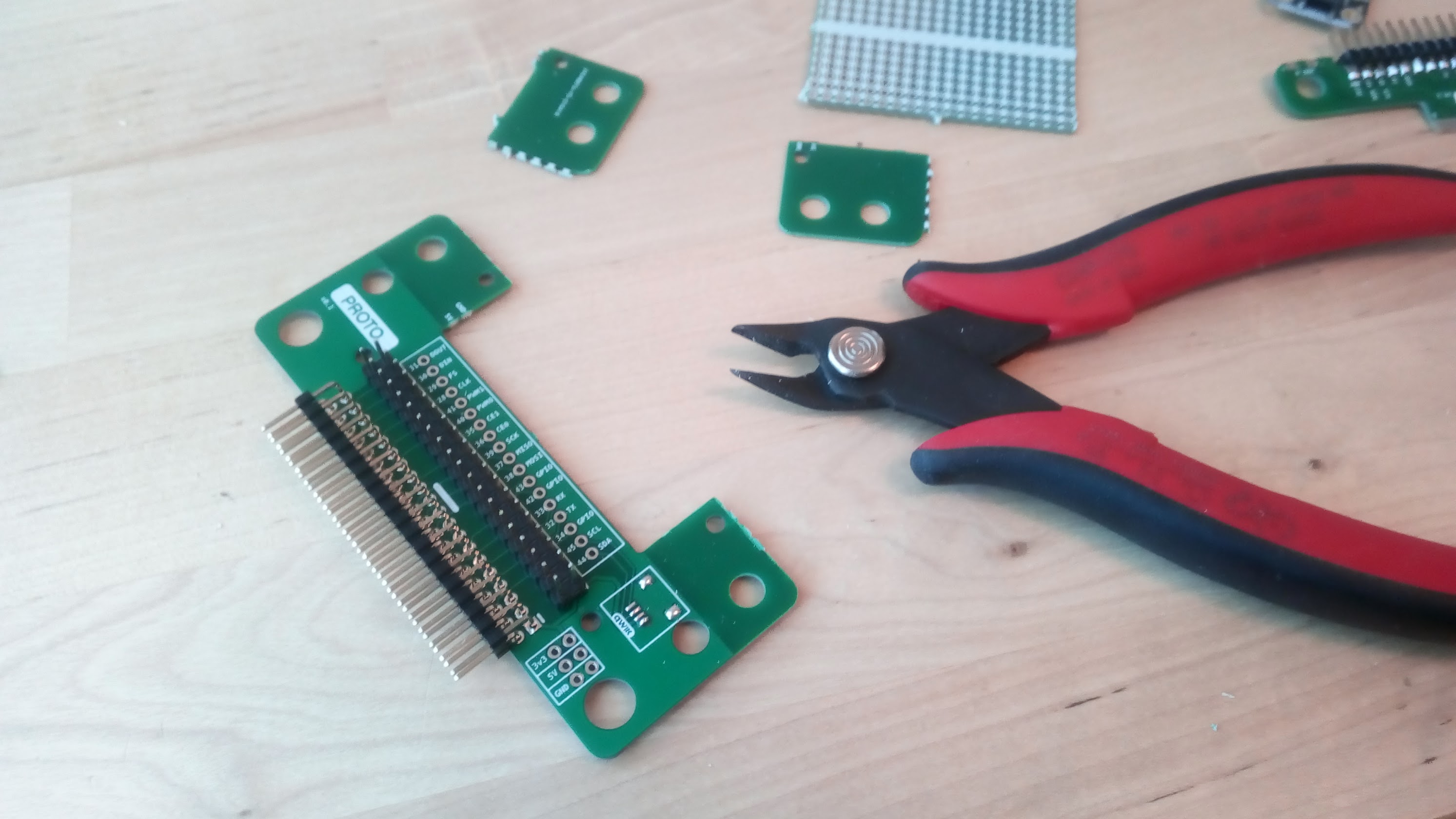
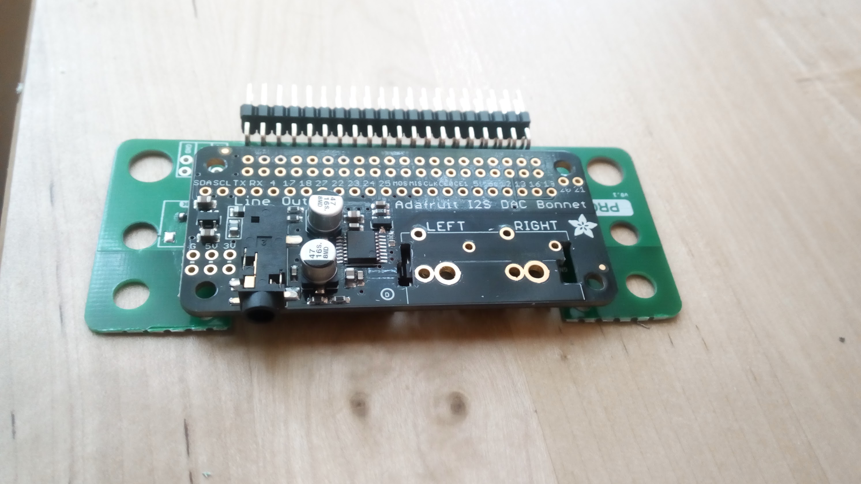
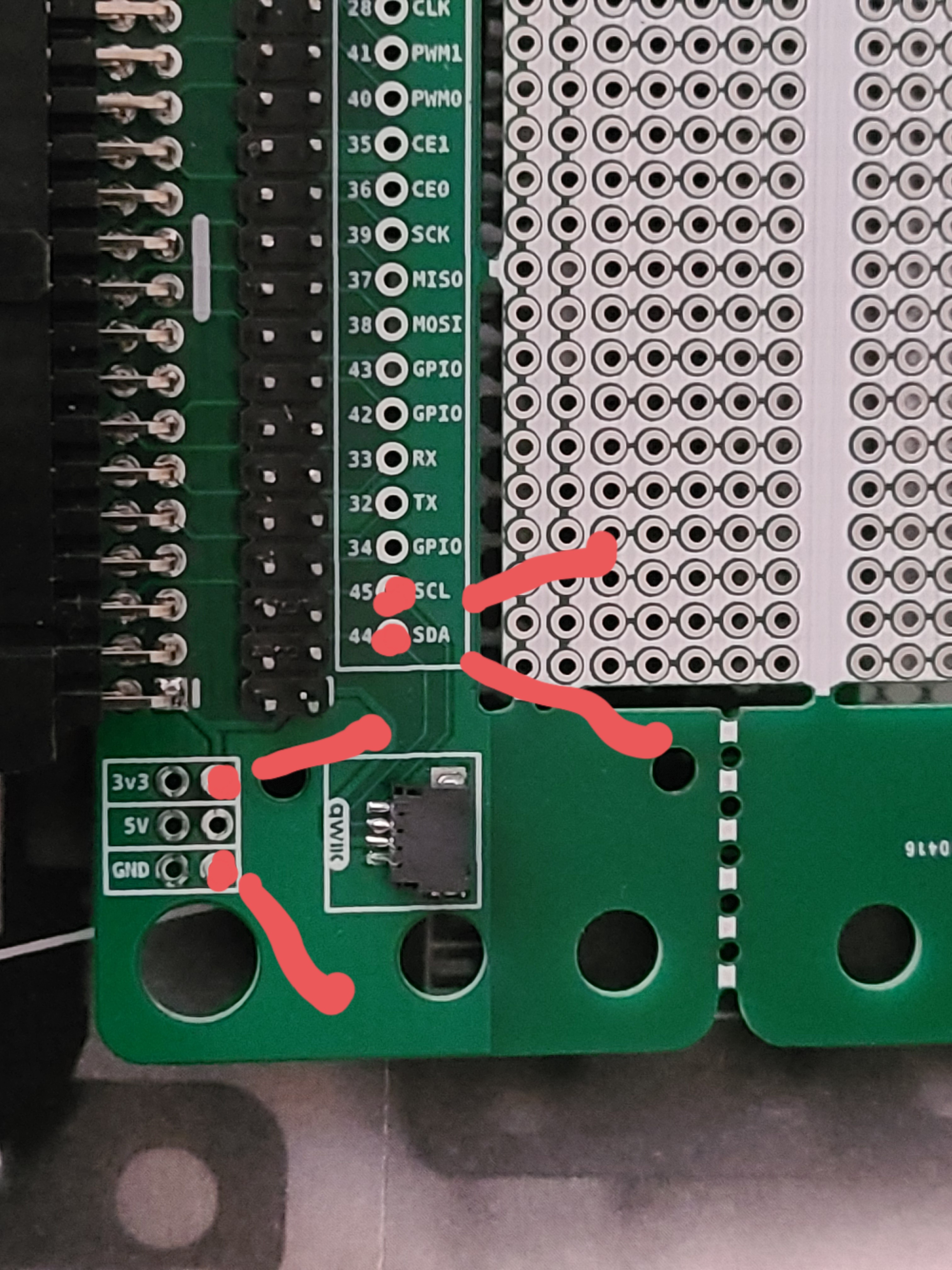
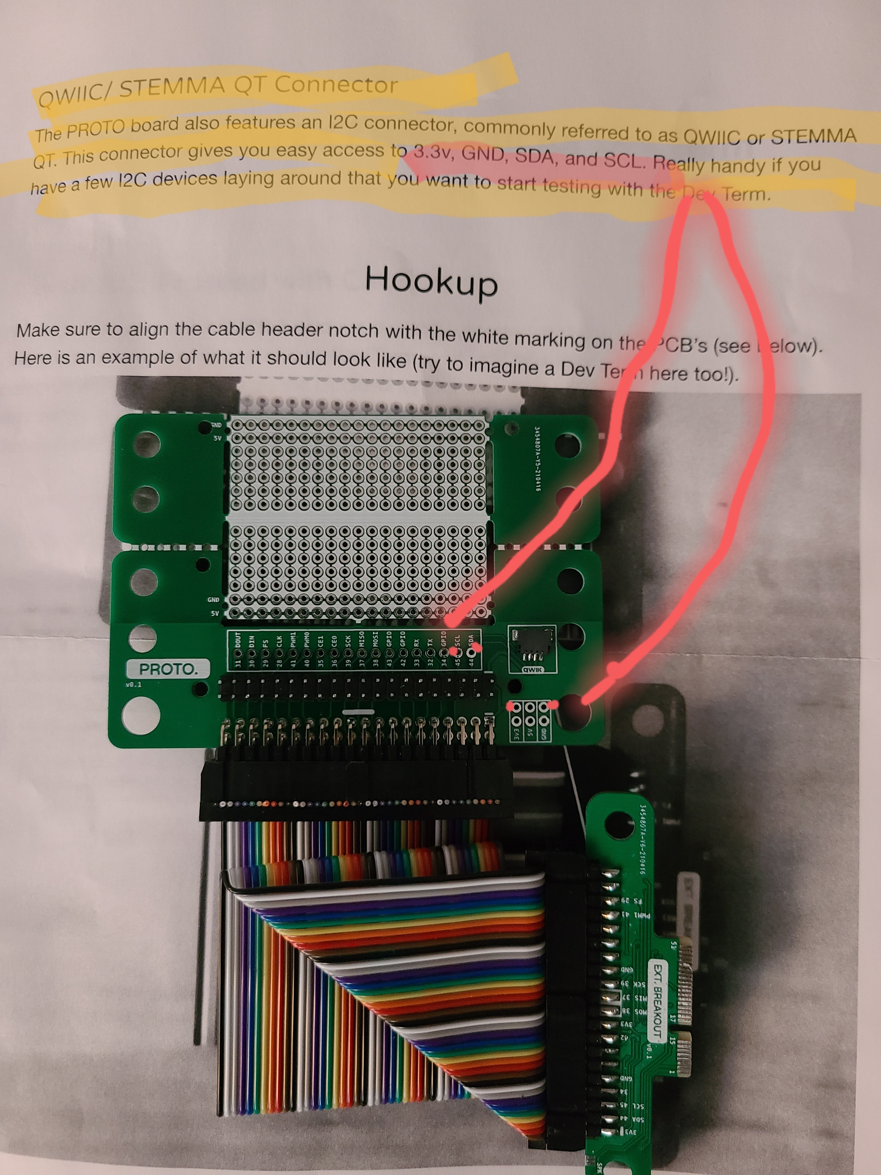
Anyway, I’m just swooping in to share a few photos of the proto and breakout board all soldered and assembled.
I’ve already got plenty more revision ideas, including an FPC connector instead of an IDC cable. Those revisions won’t come until later when the Dev Term is shipped. The goal is to have a swap-in replacement to the EXT board, while preserving USB+speakers, but gives you the freedom to swap the printer with pi hats or your own circuits/components.
Note: I’m waiting on some extra 2x20 headers and ribbon cables to get the rest of the boards assembled, and then I’ll be shipping them out!
This isH0T!!!
mounting an fpc would be sweet!!!
probably even as easy as mounting this directly:
The speakers appear to be touch contact to the ext board. preserving that function might be relatively easy as laying contacts. Preserving one usb port as normal for regular external access and making one other usb port function internally also sounds like a fantastic idea for this “upgrade.” You got me even more excited now about your work than I was before.
Ah you noticed! When I was deciding where to put the speaker solder pads for the breakout board, I tried to align them where the EXT speaker pads would be… I’m not sure if I got it right, but it’s possible this first EXT breakout will make correct contact with the left speaker.
Yeah. I wholly expect you to wait to get an actual offical ext board in hand before you’ll be able to do it properly. I do find it amusing how both the L and R on one half of the DT.
Lovely. I hope you’re still planning to do additional versions which keep the USB connectors and only free up the camera and printer pins. If so, I’m totally in the market for that - even for this version, but I’ll wait until I have the thing in hand at least.
You bet! I’ll need to get the Dev Term in hand before designing that revision. It’ll also be good to get community input after everyone starts tinkering.
@DustinWoods man, we need to design a 3d printed socket that we can install in the devterms butt. would be nice to just “dock” the thing into some other hardware
no one knows yet… however, on that note, I’ve submitted a mass of technical queries formally, this being one of them… Once I receive a reply, expect for me to share my findings.
The USB debug port on the EXT board is documented in the schematics.
There is a serial-to-usb chip on the EXT board, and the serial lines go straight to the core module on the main board.
So to clarify, the usb debug port is for serial talk directly to the core module.
Also, one could fashion a custom ribbon to length with the desired connector and print a mount for the printer port. Gutting out the printer for the gpio.
I’ve made such cables for a few pi projects
I’ve played with the idea of possibly mounting a noir cam with an ir bulb in the printer slot if there’s room after gutting the printer.
Also… apparently some of The gpio pins are swapped on the dt as opposed to the rpi… so any coding done this wise should be put through a sed script or something to fix the gpio pins for the rpi.