Cool, but I need to be able to communicate with an MQTT server, how would you recommend I do that without a Pico 2W?
For anyone who might be interested in an RTC outside the case, here are a couple of programs to manage a DS3231 RTC mounted externally on a PicoCalc.
What are you using MQTT for? I’ve been playing around with talking to a broker (had to get the upstream dev to fix a bug with displaying the topic of a received message), so wondering what other people are doing with it.
Home automation, gathering data from sensors, that sort of thing.
Can you run your 2W at more than CPUSPEED=200000? I can’t.
Me? I have never tried!
The only time I used MMBasic was to make sure my PicoCalc was working after I assembled it.
I’m working on a hobby project and not using any of the environments currently available.
No matter what environment you’re using, you can always use a burst of speed.
1 Like
Ha! You got some humour to me right when I needed it. Thank you for that!

4 Likes
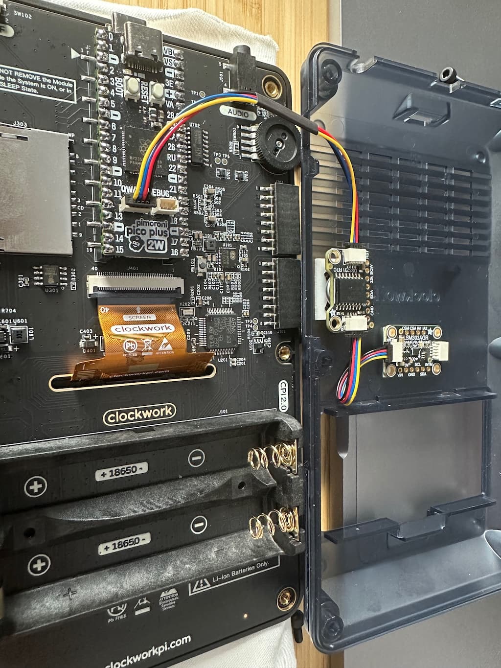
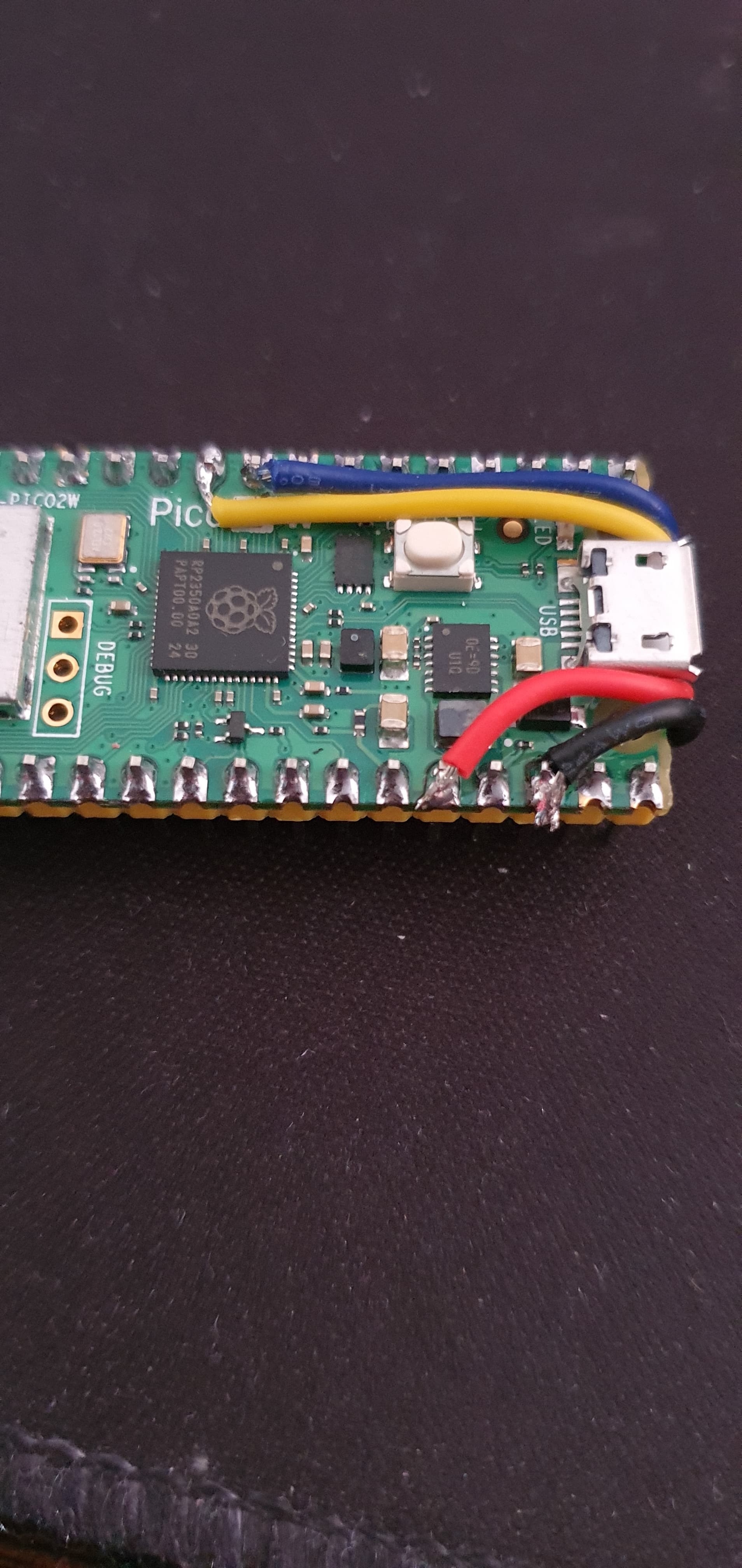
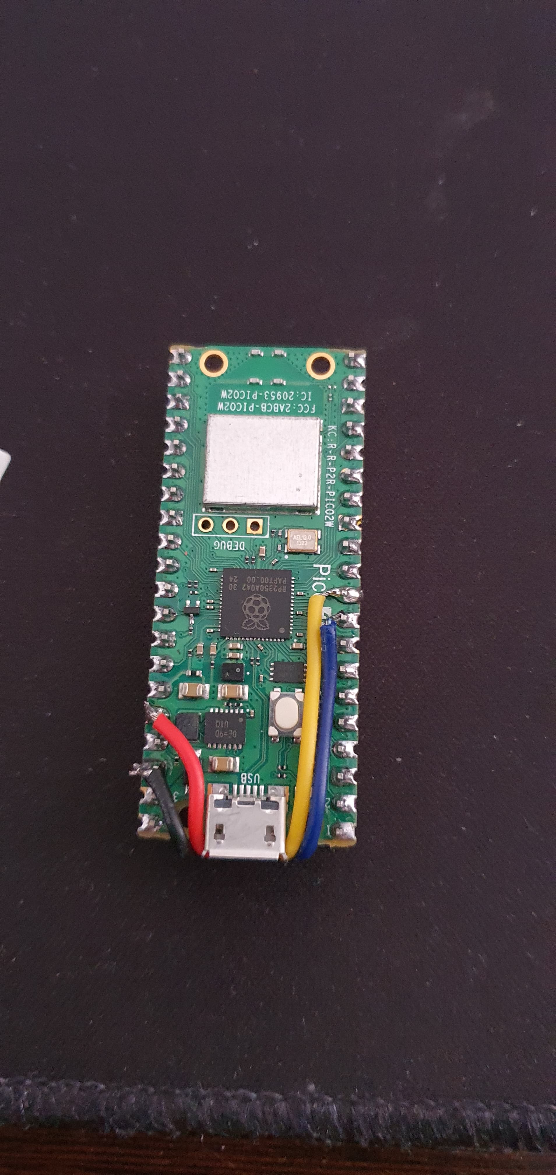
It makes sense to me to solder wires directly onto the Pico module’s pins to access the I2C bus. Just like @zedr0k did. Because the CPU modules are cheap and more easily replaced.
Perhaps solder half of a Stemma QT cable to the Pico, then run that to an Adafruit passive 5 port Stemma QT hub , and plug interesting I2C devices into the hub:
3 Likes
I added the RTC leads directly to the Pico for the same reason: They’re cheap and a day or two away.
1 Like
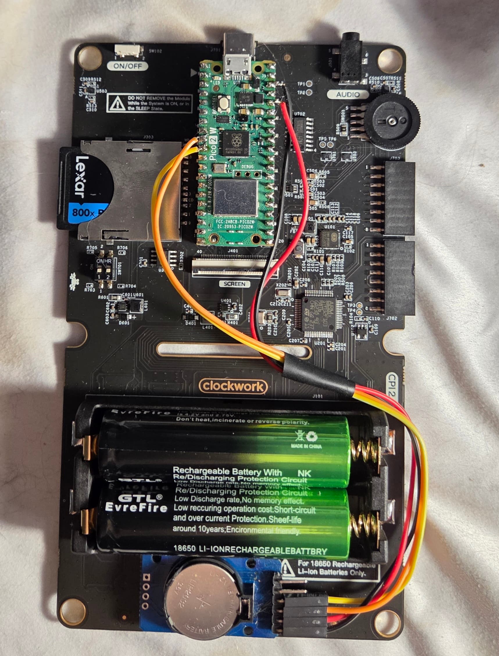
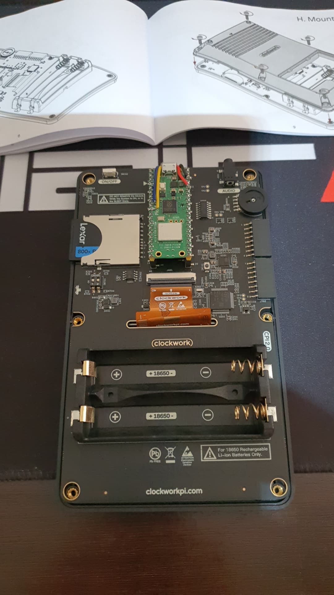
I decided to mounting the RTC below the battery holder with a bit of foam tape. It was an empty space and it fit!
5 Likes
Nice!!!
Some RTC modules include 32 KB of onboard EEPROM. Can MMBASIC access that memory? If so, how should the module be wired to the RP2040 to make use of it?
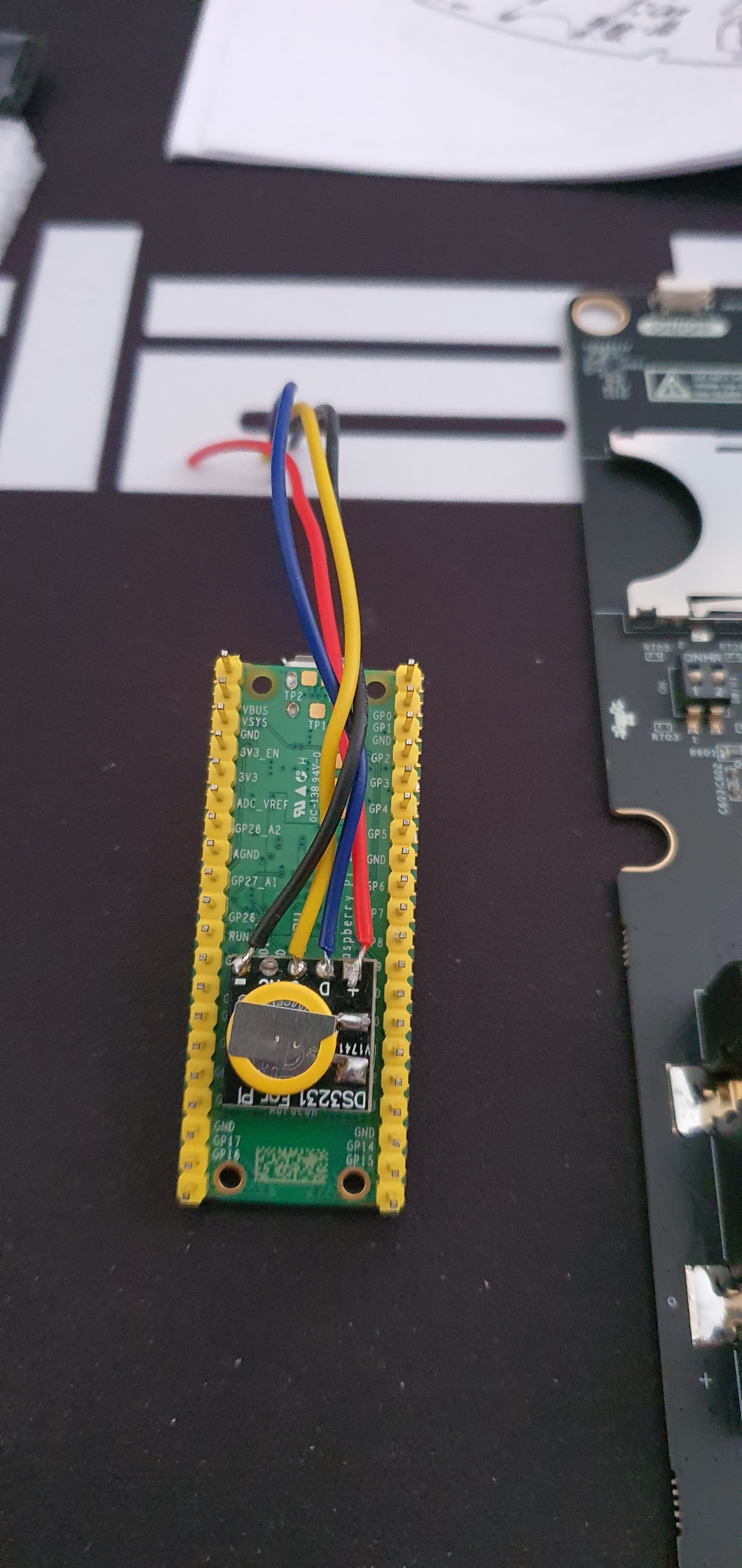
Absolutely if you can access the registers the memory is similar. Sometimes a separate i2c address. Check out the datasheet for the device. I wired directly to the Pico socket so the core could be easily removed/upgraded… Note I used VSYS for supply rather than the 3v3 out as hopefully more current available for further daisychained modules in the future (max 2A via an onboard fet switch but no idea what the picocalc is taking for itself).

2 Likes
the ds3231 module I have have an eeprom, and I think it defaults to address 0x57 on the I2C bus. Can you access the ds3231 @ addr 0x68, you probably can access the eeprom too… ![]()
2 Likes
Awesome! That’s great news.
I still don’t have my PicoCalc yet, but I assume it will be shipped soon.
In the meantime, I’m exploring alternatives and ideas to implement. I’ve “played” a lot in the past with Arduino and I²C modules, so I really like the idea of doing these things on the PicoCalc.
Thanks for your answers!
2 Likes
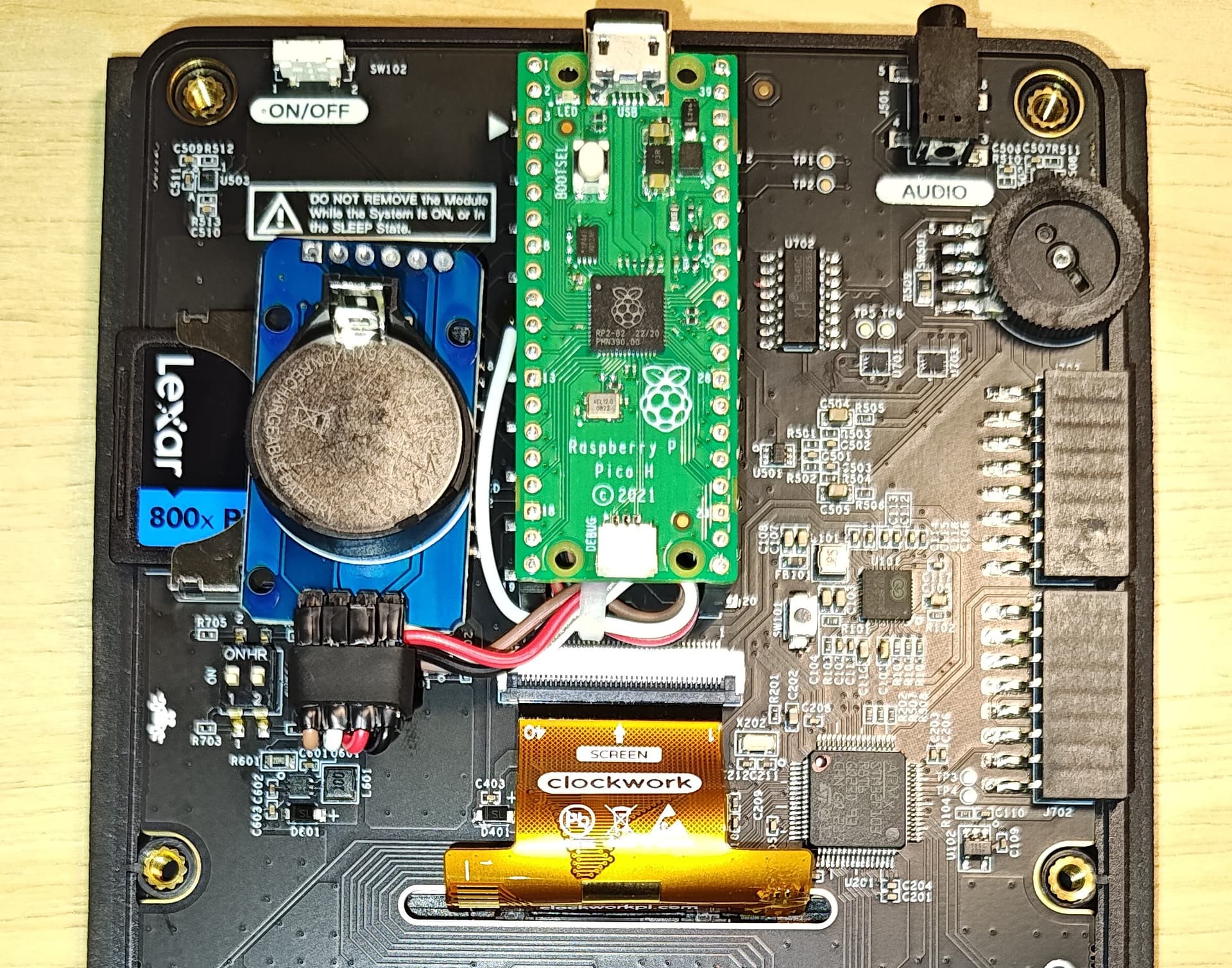
Did mine the same as Katana at the top of this post. Decided to attached wires to the Pico board. Figured I can get a replacement Pico 2 faster than a PicoCalc main board if I mess it up. Went OK and only needed to set the RTC auto enable and set the time, all worked fine.
5 Likes
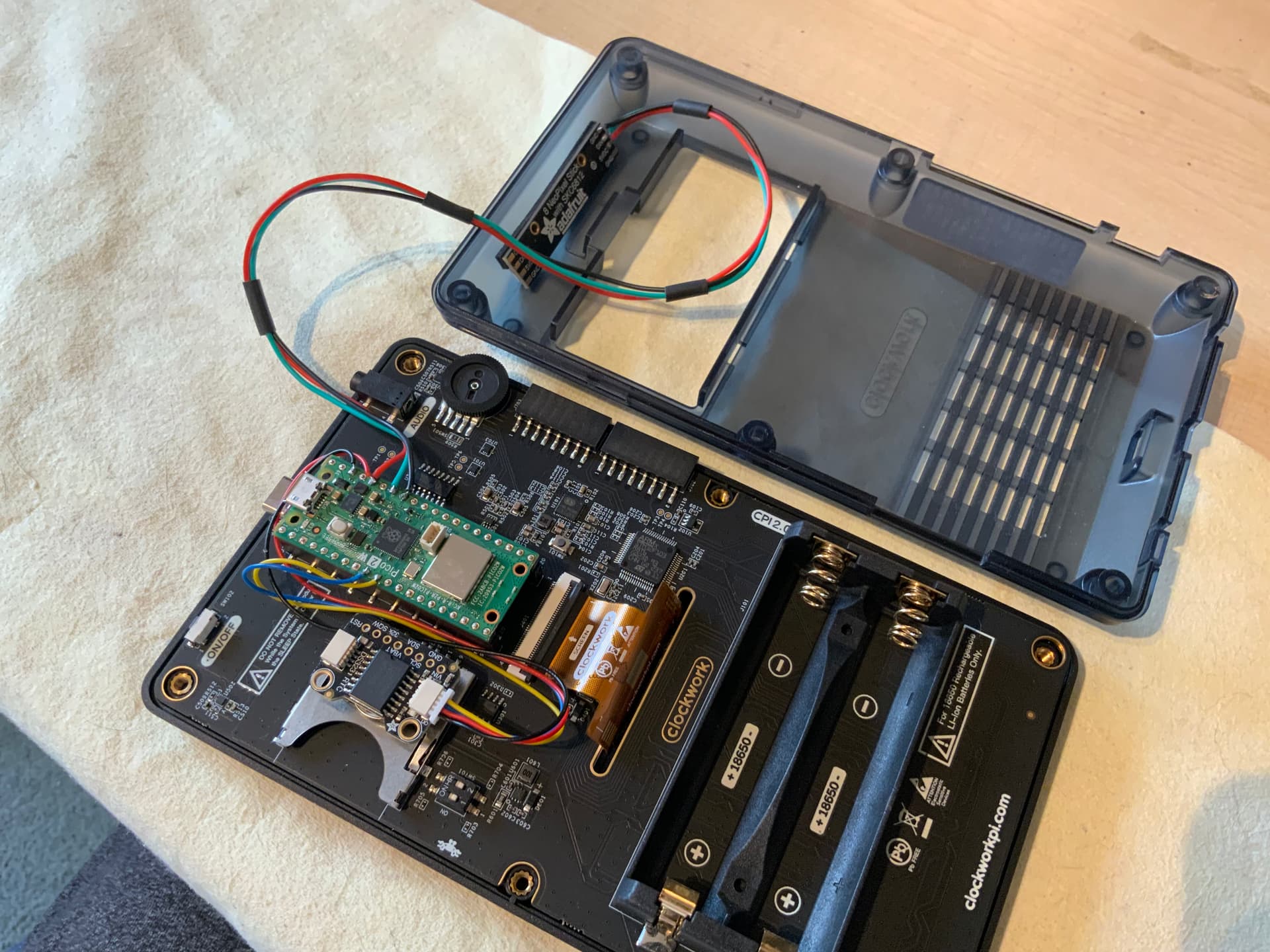
Well. I’ve decided to install under pico 2 W with RTC tiny board. Very clean installation. I used double side tape to fix under pico board. See image.


7 Likes
I didn’t bother with ‘option rtc auto enable’, preffered to just ‘rtc gettime’ once at every switch on from my autorun program. Saw no need to give the picocalc/mmbasic even more to do.