For the CM4 is there really any reason to lift motherboard WiFi chip or cut traces on the motherboard? Im still pretty new to hardware mods like this so im wondering if im missing something.
The CM4 attaches to an adapter that then plugs in to the SODIMM socket on the motherboard, that means all of the connections are right there in the open on the edge of the adapter. My idea is to solder jumper wires to the very top of the GPIO pads and cover the rest of the pad with solder mask or kapton tape so they never get to the motherboard in the first place. I figure this way my motherboard is fully functional for other cores.
Is there any reason this wouldn’t work compared to cutting the traces on the motherboard or lifting that chip?
If you do not have access to hot air, even just removing power from the MB WiFi (cut one single trace) may suffice actually. If the chip does not power on, no data is transmitted and the bus is free to use for GPIO.
Yes, hijacking the signals would work as long as they don’t make the connection to the MB. But to make sure that doesn’t happen you still need to cut the traces on the adapter before they get to the connector or after they leave the connector on the MB, assuming they are accessible. You’ll have to check the schematic for the MB, adapter board and compare them to the physical boards to see if it can be pulled off.
In short you need to study the schematics and physical boards to see if this can be done.
And there is still the question of whether or not the adapter board exports the needed signals to the MB socket. This is called in to question by what you mentioned about needing a CM4 with WiFi. This is all moot if those signals are buried on BGA pins of the SOC. Most SOCs I’ve looked at use BGA pins. I’d have to look at the CM4 to know if it does.
I don’t understand; if we power down (cutting power or GND trace) or remove the WiFi module from the MB, the GPIOs on the 40-pin GPIO header are going to be free to use, no?
You mean balls?
It’s nice / comforting to see though, that the CM4 has a nice antenna connector just like the Clockworkpi MB, so you can still connect antennas (maybe even the included one) and get good reception.
It may be worth breaking that connector out to the shell’s outside to connect a beefier antenna via SMB, though. Applies to the MB WiFi, as well, of course.
Another question, referring back to the original post: can’t you use the “52 Pins extension module interface”? Is there anything preventing you to use that for the RTC?
From what I can tell here, GPIO28 through GPIO44 are free to use on the PCIe slot, right?
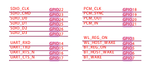
And if you do remove the WiFi chip, you get full 19 GPIOs free on the “40-pin GPIO header”:
If you end up needing the MB WiFi module after all, you can get a second MB for just $39. Then you’d have one WiFi MB and one non-WiFi with 19 free GPIOs.
Another idea: if you populate the mini PCIe slot for a 4G module and don’t want to lose MB WiFi, you do get another audio port on that 4G module. So you could remove the MB audio and get 4 GPIOs, in case that’s enough for you:
Yes, if you remove the WiFi module you gain the GPIOs. But that wasn’t the question @USFrozen was asking. I would also say that I would have some concern that an unpowered WiFi module sitting on those lines might inject some noise. But my understanding of how the chips are actually made is extremely minimal, so it could very well be a good solution.
Assuming that the CM4 adapter is actually providing those signals. I have not attempted to verify that either.
Yes, I want the printer, speakers and USB ports so I want to leave the “ext module” intact and connected. The I2C bus for the EXT module is brought out on the camera port. I don’t see anything on that board interfering with address 68H. Since I have no desire to have a camera my plan is to tap into that. Its just going to take more time, ducking and probably more creativity.
To clarify my specific needs: I just need access to an I2C bus… which is usually stupid simple. Imagine my surprise after finding and ordering pieces to work with these awful connectors that it didn’t work. Turns out the devices on the MB attached to the I2C bus also use address 68H. And there is nothing I can do about that.
The whole point of this topic was to start the discussion about what GPIO was actually still available on the so-called GPIO connector and to act as a warning for others looking to take advantage of it. Mission accomplished!
“Balls” / “pins” same difference. I italicized the word because its not the exact correct word to use. But even novice readers will likely understand what I wrote.
Good point; sadly I just discovered that the CM4 adapter has no schematics or PCB files on GitHub (yet?).
In case they thought of that (that the CM4 has WiFi already) and left the GPIOs free, that would be great news for CM4 users.
I agree, and I do thank you for that. It’s very good to know that this issue exists.
If you’re referring to the GPIO availability, its all consumed unless you remove the extension module and put your own thing there. If you’re referring to the CM4 schematics I still can’t find them. If you want to know if the CM4 gives you more GPIO, all the main and extension module connections would remain the same, so anything exported to the GPIO header would still have all the same hardware attached, yet they might not actually be attached to something on the CM4 module.
I don’t expect anything will change.
I don’t own a CM4 module so maybe some GPIO can be drawn off of the module itself.
I just noticed this was DevTerm and not Uconsole, sorry!
I think the CM4 adapter schematic in PDF format is here:
I’ve been looking at this like the rest of you, thanks for your fantastic chart @yatli. I think that we have access to general GPIO as well as SPI and other features on the PCI via the GPIO28 to GPIO40ish connectors, as far as I can tell from that schematic and the CM4’s pinout itself.
But I’m not 100% sure, there are some weird discrepancies in that linked schematic I think.
I’d love for us to figure this out! The fact that the camera and extra USB4 aren’t even given tracks and bare pads on the 4G board and bare board bugs me, how are we supposed to use them!
@Scriven42 thanks for the schematic link. I did/would not look in the uConsole repo for it, since from what I’ve experienced here it predates the uConsole by quite a bit. These guys aren’t the best “librarians”.
According to the schematic a significant amount of the capacity of the rPi-CM4 is not being utilized, specifically its not connected to anything or being brought out in any way. Only what is needed to fulfill the needs of the main board and extension connector. This isn’t surprising, since it appears that the main board was originally designed for a CM3. That means the I/O of the CM4 is being reduced to that of a CM3.
With that said @yatli’s chart still holds. With the clockwork extension module plugged in everything on the 40 pin gpio connector has other hardware attached. For my RTC project I was going to plug into the “camera” socket on the EXT module and use the I2C bus there. I have no desire for a camera.
I don’t know that there is anything left to figure out. If you want to reach the unused I/O of the CM4, judging by photos and schematics, it appears you’ll have to brew up a different adapter or some kind of piggy-back arrangement (which there likely isn’t any room for) with additional connectors to export the orphaned I/O.
Or you can ditch the EXT module and pull I/O off of the EXT connector. I don’t have a uConsole so I am assuming that they have an EXT module plugged in. Since the DevTerm and uConsole use the same main board the connectors are the same in both cases.
I’m not sure if I’ve made a mistake or not, but I’ve gone through the various schematics for the uConsole and done the same thing as @yatli’s done, but for the CM4 only, and things look different and possibly MORE frustrating?
From what I can tell, both the camera (CAM1) and a bunch of unused GPIO is sent to the PCIe connector, and are then just trapped on the 4G board…
I found it very confusing to map the net changes to try and keep track of things, they change from CM4 to DDR, and from DDR to MainBoard in some cases.
Oh, I wonder if this even belongs here or should I post this in uConsole forum? lol
NOTE: I don’t have a g00g account. The made a security decision on my behalf, without consulting me and locked me out. I’m already fed up with them so, I’m content to leave it at mutual hate.
I took a further look at the uConsole and see that they don’t use the DevTerm “EXT” module but instead provide the 4G adapter. Anyone familiar with the uConsole is probably saying, “DUH!!” Since the DevTerm and uConsole EXTension hardware differs the uConsole forum may have better info. I’d also hazard a guess that the 4G module leaves more GPIO available. I’m pretty sure the DevTerm board was designed to use everything the main board didn’t. But if memory serves nothing from the PCIe connector shows up on the “GPIO connector”.
Hmm… might be interesting to put this 4G module in a DevTerm if you can obtain it separately and you don’t want the printer.
As for tracing it through I’d start a spreadsheet. (Sorry I can’t see what you have.) I’d start with the SOM connector on the main board and list pin numbers in one column, signal names in another. I’d disregard anything not useful for GPIO purposes: Power, RAM, … I’d do that simply to cut down on the work. If those things hold interest for you, then by all means trace away.
I’d use additional columns to track label changes and where those signals come out on different connectors.
Unfortunately I find that ClockworkPi is not particularly friendly to hardware hackers. The issue that prompted this topic, the use of FPC and PCIe connectors without supplying suitable breakouts, the warranty issue, disappearing SOMs, insane delivery times, broken software, … They have all soured me on ClockworkPi. Its bummer because the actual hardware and cases look to be “class”. But its like they can’t be bothered with the mundania of making it work or supplying trivial components to encourage the “maker” spirit their ads seem to want to foster. Without any available GPIO on their GPIO connector … its kind of moot. In short they oversold what they had to offer.
FYI: I Found that https://tinkersphere.com/ has a broad selection of 6" FPC ribbons and appropriate breakout boards. It won’t help you with the PCIe connector. But it will help with those other connectors. Just don’t sneeze or you’ll break the damn things.
Anyhow I don’t suspect I’ll have any time to further chase the uConsole hardware. Good luck!