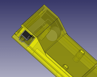
EXT Cartridge Module

Not all interrupts can wake up the chip

Good point! On the T4.0, all pins can wake it up.

There are still two free SPDTs on U9… cough cough

The only sensible thing I can come up with is switching between device and host mode via these.
So in Mode-A, it’s a host via the USB hub, and in Mode-B it’s a device via the Teensy.

I have no clue to mux the Teensy between cartridge or host using only what’s left.

Generally got a bad feeling about switching between those tough, I wouldn’t do that physically with a SPDT, bound to confuse the bus somehow. On the other hand, it should be no problem at all.
Also it’s def. harder to route and I want to order boards sooner than later.
I’d say it’s an edge case that doesn’t warrant a general feature. If you need a device, put it as a chip in your cart or bang it out for v1.0. Excuses excuses :slightly_smiling_face:

Lastly, I just noticed that there’s some space for a coin cell holder where the cam connector was. Having an RTC that keeps time would be nice to have in my experience.

I’d say with that, all the features for v1.0 are decided, looking at the first post it has come a long way, anyway.


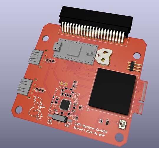
Update: Routing so far is complete, DRC checks out and all that’s left is the silkscreen.

As the CAM_EN and CAM_LED pins are no longer a thing, I used those for CART_MODE and TEENSY_WAKEUP. I think this is worth a shot, will order this next week.
2 Likes

Fantastic! Really looking forward to it.

Oh btw, on second thought, I think now that we have a MCU, there’s no need for DeviceTree mods.

We can create a platform device that reports device connect/disconnect to the kernel.

Conceptually, it’s not different from USB, PC-Card etc., except that Teensy is the PHY.

I got two simple boards completed today: the RPi interface and a simple passthrough to a header.
Luckily, the only functionality missing from the RPi card is SPI2, but you got ADCs and CAN.
Win some lose some :smiley:
As the EEPROM I selected the M24M02
Here’s the pinout:

Meanwhile, I started the mechanical design while the parts arrive.
It is keyed, so no worries that you plug it in backwards.
Lazy Susan of the design so far

Based on the C64 design, I’ll 3D print those tomorrow and do a test fit.

Curious, I see you have the DT model imported into FreeCad. Did you convert it to features or just mesh?

I tried to convert it to solid and it ate a few hours and gigabytes and gave up(

Did you convert it to features or just mesh?

I just imported the mesh, and then reduced it even some because I’m computing on a potato by today’s standards.

Good news: the cart design fits nicely, parts are ordered and PCBs are in production.
In a months time I might have the first prototype assembled.

1 Like

Oooh nice. You gonna solder the parts by yourself?
The skills required for soldering smt stuff are beyond my pay grade ($0).

2 Likes

Oooh nice. You gonna solder the parts by yourself?

Of course!

Here’s a sneak peek of the RPI and passthrough cart PCBs.


Edit: It appears that I sent it too soon, that stray trace on pad 10 wasn’t intended.
Nothing a little bodging can’t fix tough.

Nah SMT is easy if you’re sticking to one of the larger component sizes like 0805, Don’t let it intimidate you its just different from how you do thru-hole. Once you’ve got the knack it’s ok

Ha thanks. It’s just that… I had too many expensive failures with SMT. XD

Boards arrived this week and I already got started coding on the Teensy firmware.
So far I embedded Lua (instead of Micropython) to use as a scripting environment for configuration and playing around, with binary upload support. Works great so far.

Slight setback on the SPI communication with the DevTerm tough. First, I didn’t connect SCLK. No worries about that tough, I soldered a bodge wire to the PCIE connector.
What’s more worrying tough is that the Zephyr driver for SPI flat out ignores a slave configuration and instead configures it as a master. So I actually had two SPI masters sending on the bus at the same time.
Since then, I noticed that CE0 (GPIO36) doesn’t pull down the signal anymore, fearing that something fried. SCLK and MOSI tough send as expected.
I did use the SPI library from NXP directly later, but it doesn’t respond to SPI transfers, most likely due to CE0 being high permanently.

I also tried printing with the normal EXT board, but the system powers down display cuts to black and the system is unresponsive as soon as I send to /tmp/DEVTERM_PRINTER_IN. Unexpected to say the least.
Maybe I’ll try the debug serial once I get around to build the CH34x driver for Linux.

Update: I couldn’t figure out why I can’t connect to the UART chip so I soldered some wires.
Debug serial shows nothing when attempting to print. I’m all out of ideas regarding the printer.

3 Likes

FYI there’s also uLisp if you want some parentheses: uLisp - Lisp for microcontrollers

What’s more worrying tough is that the Zephyr driver for SPI flat out ignores a slave configuration and instead configures it as a master. So I actually had two SPI masters sending on the bus at the same time.

Horror story…

1 Like

Small Update on the current Progress

The USB hub works great so far, and mechanically everything fits nicely.
Tough I’ll have to prototype on a breadboard until my replacement A06 arrives.

Good news is that PCBWay reached out and sponsored the next version of the PCBs.


I added an extra header for the second downstream USB of the TUSB2036 originally leading to the Teensy’s USB2 (Host pins). Theoretically you can use the MCUXpresso HAL to configure it as a device, but right now I won’t bother with that and use the new header to connect it to the Micro-USB port.

With that batch I also ordered one for a thermal printer cart. It’s happening for sure, I quite like that gimmick and will do my best to cram it into a module. Here’s a rough draft of the form factor:


Here’s the PCB:

Sadly I can’t make it any smaller, as the printer module itself does not fit height-wise into the cartridge slot.

You can also follow this project on hackaday.io. I think updates should belong there and this thread should be used for discussion.

Speaking of discussion, the SPI protocol is still in the early stages. Right now it consists of a simple command/argument pair sent by the master, and the slave sends back a response and its command word. Tacked onto this is a 32 Byte buffer for additional data.

Master Frame:
| Command:u32 | CommandArg:u32 | TxBuffer:u8[32] |

Slave Frame:
| LastCommand:u32 | CommandResponse:u32 | RxBuffer:u8[32] |

Highly inefficient for setting GPIOs, as it should only take 2 words per frame, but when I tried implementing a protocol with differing transaction sizes the receive buffer got too wonky and data started/stopped wherever in a ring-like fashion. Maybe I should include a magic start/end byte and try to compensate.

Lastly, the PicoBlade connector I ordered for the fan doesn’t fit sadly.
Found this one which looks like a better fit, but I’m not sure. There’s thousands of connectors out there and my patience for looking for the correct one ends with this.
I tried reaching out a few months ago about the various connectors, with no reply. Can’t blame them, my inquiry isn’t that important and customer support is hell in general.

FYI there’s also uLisp if you want some parentheses

Oh no :))))))
Too late now to change anyway, but uLisp is interesting.

Horror story…

Yeah, F for my A06. Lesson is that you don’t go gung-ho with your expensive core module and instead use a raspi you don’t particularly care about.

5 Likes

I literally dreamed about using the printer module externally a few days ago. Weird but that happened :smiley: I imagined having the motor and printer part mated, and the ribbon cable hanging at the expansion port, but the ribbon cable being not long enough – which might be a problem for the real thing you’re proposing. Maybe make the PCB a bit taller?

I just registered on hackaday. Do please remind us if there’s an update over there!

Maybe I should include a magic start/end byte and try to compensate

Yep, you’ll definitely need a self-synchronizing protocol even for a fixed data format. Currently the Command acts as the sync byte but it’s not guaranteed to work.

Maybe MIDI-like 7-bit protocol? The 8th bit is then the sync bit.

1 Like

ribbon cable being not long enough

Nah, I’m sure it fits, in fact the PCB had to be shorter than usual because the ribbon cable is too long and would unnecessarily flex.

self-synchronizing protocol even for a fixed data format

SPI tough is a synchronous protocol, but it surely doesn’t hurt to add some layer of synchronization.

Maybe MIDI-like 7-bit protocol? The 8th bit is then the sync bit.

Not too keen on the idea of having only 7 bits per byte, I need a round 32 bits for a GPIO update and splitting it into 5 bytes seems a bit over-engineered. MIDI is cool but it’s designed with a different physical layer in mind.

Master Basic Frame:
| StartMagic:u8 | TransactionNo:u16 | Command:u8 | CommandArg:u32 | EndMagic:u8 |

Slave Basic Frame:
| StartMagic:u8 | TransactionNo:u16 | CommandStatus:u8 | CommandReturn:u32 | EndMagic:u8 |

Master Buffer Frame:
| StartMagic:u8 | TransactionNo: u16 | RxBuffer[N] | EndMagic: u8 |

Slave Buffer Frame:
| StartMagic:u8 | TransactionNo: u16 | TxBuffer[N] | EndMagic: u8 |

For updating the GPIO, the basic frames should be enough.
If you want to send something through to a bus e.g. SPI,
or if you want to issue a Lua command then it needs four transactions:

DevTerm                             DTC-Module
-------                             ----------
   |        == Transaction 1 ==         |
   | 1.a Basic Master Frame             |
   | ['s', tno=1,cmd=0x20,arg=32, 'E']  |
   |----------------------------------->|
   |                                    |
   | 1.b Basic Slave Frame              |  Slave Frame for previous
   | ['s', tno=0,cms=ok,cmr=???, 'E']   |  command
   |<-----------------------------------|
   |                                    |
   |        == Transaction 2 ==         |
   |                                    |
   | 2.a Basic Master Frame             |
   | ['s', tno=2,cmd=NOP,arg=X, 'E']    |
   |----------------------------------->|
   |                                    |  Slave Frame for current
   | 2.b Basic Slave Frame              |  command, next slave frame
   | ['s', tno=1,cms=ok,cmr=32, 'E']    |  is set to be a 32Byte buffer one
   |<-----------------------------------|
   |                                    |
   |        == Transaction 3 ==         |
   |                                    |
   | 3.a Buffer Master Frame            |  Here, we send the SPI data
   | ['s', tno=3,tx=[...], 'E']         |
   |----------------------------------->|
   | 3.b Buffer Slave Frame             |  Since we have nothing yet,
   | ['s', tno=2,rx=[0x0], 'E']         |  clock out zeros for RX
   |<-----------------------------------|
   |                                    |
   |        == Transaction 4 ==         |  Receive the buffer data from
   |                                    |  the SPI command
   | 4.a Buffer Master Frame            |  Frame is only used for 
   | ['s', tno=4,tx=[0x0], 'E']         |  clocking out data
   |----------------------------------->|
   | 3.b Buffer Slave Frame             |  Here is the data from
   | ['s', tno=3,rx=[...], 'E']         |  the SPI call
   |<-----------------------------------|
   |                                    |

The synchronizing protocol is frame-based, whereas SPI synchronization only guarantees byte boundaries. So a byte could end up either dropped, or transmitted successfully, or transmitted wrongly (e.g. two flips to fail the parity).

Using ack alone like in your example will guarantee frame boundaries (frames are either dropped, or transmitted as a whole), but errors will still occour. To greatly lower the chance of accepting a wrong frame, checksum can be used.

Recommend replacing the frame end magic with 8bit CRC.
Recommend encoding frame type and frame seq no. into starting byte. As long as you don’t need interleaved transactions, you’ll only need a flipping bit for transaction no.
The frame type may imply frame length (a few kinds of lengths), or occupy a length field.

1 Like

Good suggestions! I now used the magics’ lower nibble for the frame sequence and upper for the frame type, and of course a CRC for the end byte. The details are over here.

So far it’s seems to work out with dynamic data sizes, tough I have a bug with I2C1 on my Teensy. The SCL line won’t clock. I’ll later check it with another I2C.
and reading/writing to I2C works now. Previously I hooked up the BME280 wrong resulting in a lost bus arbitration error I suspect.

Meanwhile I think I managed to source the I2C EEPROMs from eBay. Crazy how short we are on some components.
Speaking of EEPROM: I think additionally to the Lua bytecode, wouldn’t it be neat to have a Python-Script byte-compiled as well? Thinking of the printer cart here, it could be cool to have at least the text-based interface available without any sort of installation.
Other than that, I’m not too familiar with device trees as in the HAT-system, so I can’t judge how much utility this would have.

Updating here since I am stuck.

The kernel driver for the module works so far on a Raspberry Pi 3, but now I want to test it on the DevTerm.

For this, I’ll need kernel headers, and that means recompiling the kernel as far as I understand it.
I’m trying it out on the CM4 version as I think it would be the least complicated to compile a module there, and so far I can compile the kernel and install the headers just fine on the CM4 itself:

cd /usr/src/
git clone https://github.com/raspberrypi/linux
git checkout 3a33f11c48572b9dd0fecac164b3990fc9234da8
# copy and apply patch
git apply cm4_kernel_0704.patch
KERNEL=kernel8 make ARCH=arm64 bcm2711_defconfig
KERNEL=kernel8 make ARCH=arm64 -j5
make modules_install
cp -rf modules/lib/modules/5.10.17-v7l+ /lib/modules/
cp arch/arm64/boot/dts/overlays/*.dtbo /boot/overlays/
cp arch/arm64/boot/dts/broadcom/bcm2711-rpi-cm4.dtb /boot/
cp arch/arm64/boot/Image.gz output/boot/kernel8.img

After that, the system boots fine, and I can compile my kernel module, except the screen remains off.
Output of dmesg is here: DevTerm CM4 No Display dmesg - Pastebin.com
I have no idea what went wrong there. If somebody has a clue on why it fails or how to debug this, I’d be thankful.

Edit: Post can be disregarded now. I just did apt --reinstall install devterm-kernel-cm4-rpi on top and now I got everything working again, including building kernel modules.

1 Like

Sounds like you went through a lot of headache :smile:

I love the project but I am not that skilled with the details.
Can you maybe summarise the progress so far? Explain me like I‘m 5 style :sweat_smile:

Not sure what the bcm2711_defconfig include by default, but if the OSS GPU driver re missing, you will not get any display.

Also you replaced some of the device tree files, some of them are essential for the DevTerm for work properly,

I would recommend to copy back all the original dub file in place, then reboot and see what is happening, if it still don’t work check the confit.txt file that the KMS GPU module is properly selected, and then you’ll have to check the kernel config and most likely rebuild it.

Thanks for the tips! The new device tree files and everything else in /boot matched 1:1, and the config.txt was the same as pasted here.
As everything works fine now after reinstalling the devterm-kernel-cm4-rpi package I’ll try it properly once again when it comes to releasing everything after cleaning the source code up.
Currently the kernel module does work but the source is just a haphazardly thrown together, trashy pile of over 3000 lines of code, so that’ll take a while.

The system consists of 3 parts: The DevTerm, a Teensy microcontroller and any cartridge.
As the DevTerm’s EXT IOs are nice for an expansion board, and cartridges could be so much more with more IOs, a Teensy microcontroller is sandwiched in between providing more of it.
So, if I want to toggle a GPIO or read I2C, send via UART etc, the DevTerm communicates via the serial protocol SPI to the Teensy which then does then the things.
Sort of like flying a plane, you pilot it go places you can’t reach on foot.
The communication part on the DevTerm is handled by a kernel module, which exposes the additional hardware from the Teensy as Linux devices. Think /dev/ttyUSB-like for UART for example.
This means that programming for it should be trivial in most cases.
All of this works splendid on my Raspberry Pi test rig, and debugging is still in progress for the actual DevTerm. In addition, the cartridge port does have two USB lanes additionally to the normal USB ports on the side of the DevTerm, which I plan on using for an SDR cart for example. This part also works as of now.

I’m currently making a switch to the Teensy4.1, as soldering all the pads on the 4.0 is impossible to do right and I’m waiting for them to arrive. This is why my current design doesn’t work properly, in a nutshell pins 34-39 on the 4.0 are giving me trouble by not quite shorting the supply, but significantly enough in the worst case that the thing does not work properly as of yet. I know I was quite naive in thinking that could work out just because the footprint had included these. They’re quite near to each other, less than half a millimeter.

Lastly, a mayor setback happened this weekend as my SSD was very suddenly on the verge of dying and my last backup of the PCB files is months old sadly. I’ll post an update if I can recover the files.

1 Like