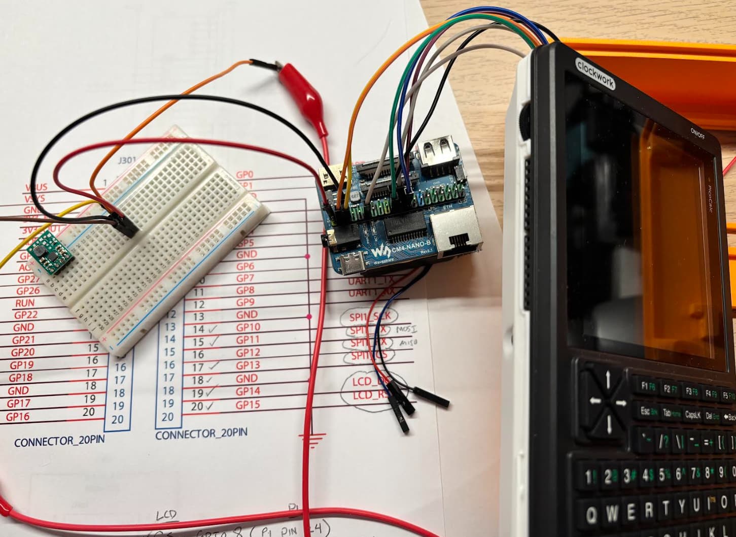
I’ve been doing some initial tinkering with a Raspberry Pi CM4 and the PicoCalc, in the hopes of figuring out a proper schematic to get the PicoCalc peropherals working correctly before spinning a board that would plug in to the Pico slot.
I used the Waveshare CM4 Nano carrier board, and worked on getting the SPI display working using the following instructions:
These almost worked (with rotated, inverted color display, that had an offset issue) – a handful of changes to the library worked to get it rotated, normal color, and set to 320x320.
I haven’t been able to figure out exactly how much current the Pico slot can source on the 3.3V rail from the schematic – hopefully it’s a fair amount (and enough for a boost to 5V near 2A), or this may be a non-starter.
I’m having some success with a ported version of the Pico keyboard driver in userland, but it’ll take me a bit more tinkering to get it working as a proper kernel driver – that’s a little outside my past experience. But, forward progress is being made!
Thanks @Rex , I’ve been attempting that, but for some reason it only appears to work when I run it from the console. There must be an order issue, or the i2c driver not available yet, or something, that I need to figure out. It’s just slow to debug when the system requires a full power down / reboot on most changes.
One of my main questions has been whether powering the CM4 would be a challenge, given that the Picocalc power circuitry looks complex, and I can’t entirely figure out how much supply current the Picocalc socket has from the schematic.
I made an attempt to power the Picocalc through a 3.3V → 5V buck/boost power supply from Pololu tonight ( Pololu 5V Step-Up Voltage Regulator U1V11F5 ), without success. For some reason, powering the Pololu buck/boost from the 3.3V on the Picocalc socket caused a very low voltage on that line, and zero output. I tried powering the Pololu buck/boost through an external supply at 3.3V, as well as just powering the CM4 directly from the bench supply, and both worked. So I’m not entirely sure what the issue is, and it’ll take a bit more research to figure out why the internal 3.3V is not working as a supply for the buck/boost.
it’s probably hitting overcurrent protection for the 3.3v line. You need to get your voltage from the vsys line, but I’m still not sure if it’ll provide the needed current after passing through the axp and switch chip.
Also, that polulu board is way undersized for your load…
Quick update: It definitely looks like the buck/boost is undersized – it doesn’t power X windows for longer than a few seconds, even when provided input from a bench supply instead of the PicoCalc regulators. I’ve ordered one that’s supposed to be good for up to 4 amps ( Pololu - 5V Step-Up Voltage Regulator U3V40F5 ), but it looks like at least 2 amps in the regime this is likely to operate in, so hopefully there will be a bit more success with that.
I am a little bit worried about the PicoCalc’s ability to source current. I haven’t been able to find a datasheet for the WAS4603 (U102) that supplies PICO_VSYS, but I located it on the board and it’s quite small, so I suspect it’s likely not good for more than 250-500mA at the maximum. The MCU_3V3 line on Channel 1 of the AXP2101 is supposed to be good for only 2A (@3.3V), which is likely only in the neighbourhood of 1.3A (@5V) with 100% efficiency – so likely closer to 1A with realistic expectations.
If that’s the case it’d likely mean that the CM4 would have to be directly powered from the batteries, though I’m not sure how fantastic that’d be while they’re charging. The maximum charge current is 1A (less than the CM4 would take, so a net loss to the charge), and I’m assuming that’d make it a bit challenging for the charge circuitry to monitor the charge level.
Awesome Work ! I was thinking of doing this type of thing with an RPi Zero 2w or maybe the more powerful Radxa, but im also not sure about how much power the PicoCalc board can supply.
I’ve (unfortunately) found that trying to use the CM4 at 320x320 resolution is a major limiting factor to usability, even with 2x downscaling to try to get more real-estate (640x640) which unfortunately makes the text almost unreadable. I’m not sure if the project is entirely viable (beyond being a novelty) with this limitation.
Dang, would this be the same situation for a Pi02w ? if so, could a Hotbutton be assigned to zoom in to make things more legible ? Or would a non GUI terminal based approach be better? Thank you
Very cool project. I’m totally new to this microcomputing space and I’ve found that I’m decent at following instructions and getting over roadblocks, but I have NO IDEA why I’m inputting the code that I am. Y’all talk about this stuff like it’s the weather…How did you learn all of this to make it second nature?
It seems that U102 corresponds to, or is identical to, the Will Semiconductor WS4603. If that’s the case, it functions as a current limiter. Based on the Rset resistor value (3.4 kΩ) connected to the Iset pin, the current limit is configured to approximately 2 A.