Foobler's "Getting Started" notes

Like some others here, I stumbled across the PicoCalc online, then hurried to order one.

$75 USD + $25 shipping. An impatient couple months waiting for the shipment to arrive in the USA, plus the worry that American tariffs would double to the cost to me, or make my PicoCalc disappear at the port of entry. But it did arrive!


2 Likes

I wish my box wasn’t destroyed at arrival. Nice! heres a few repos with good basic programs! INSCCOIN’s repo, VanzT’s repo, rlauzon54’s repo

2 Likes

As others have suggested, I taped the screen into the front of the case, holding it in the square opening with a bit of blue painter’s tape on either side, making sure to avoid blocking the power led.

I pressed the Pico H compute module into its socket before laying the base board onto the front of the case. I didn’t want to press the compute module down, flex the base board, and crack a screen underneath.

Getting the LCD flat cable into its delicate connector was a bit of a mystery, until I figured out that the tiny black piece is the hinged part that flips up for cable insertion! But I didn’t break anything.

At the hardware store, I bought a single 18650 Lithium Ion battery, and inserted it, minding the marked polarity.

I’ve posted my first power-on image. Look at all those fingerprints and smudges, some on the underside of the protective glass! That’s something I’ll have to clean up, when I next disassemble the PicoCalc.


4 Likes

As I browsed forums, I read about newer versions of the firmware, both for the Pico H and for the STM32 that manages the keyboard and battery. It wasn’t very clear how this all worked. But I managed the following upgrade last night…

PicoCalc keyboard firmware discussion…

Unofficial PicoCalc PicoMite/WebMite firmware release thread (V6.00.02RCxx) - #94 by DigitalDreams

STM32 firmware update process

Browsed the UF2 files for the latest Release Candidate version.
PicoCalc/Bin at master ¡ clockworkpi/PicoCalc ¡ GitHub

Downloaded onto Debian Linux system, then checked file integrity by comparing checksum to published value:

md5sum ~/Downloads/PicoCalc_BIOS_v1.2.bin 
2b1f3dd57c168d59096e81b7180dd530  /home/foobler/Downloads/PicoCalc_BIOS_v1.2.bin

Grabbed an STM32 flasher:

sudo apt install stm32flash

Then, with the PicoCalc opened up, set the tiny DIP switch #1 to on, plugged in a USB-C cable, and ran the flasher:

sudo stm32flash -w PicoCalc_BIOS_v1.2.bin -v -S 0x08000000 /dev/ttyUSB0
stm32flash 0.7

http://stm32flash.sourceforge.net/

Using Parser : Raw BINARY
Location     : 0x8000000
Size         : 65536
Interface serial_posix: 57600 8E1
Version      : 0x22
Option 1     : 0x00
Option 2     : 0x00
Device ID    : 0x0410 (STM32F10xxx Medium-density)
- RAM        : Up to 20KiB  (512b reserved by bootloader)
- Flash      : Up to 128KiB (size first sector: 4x1024)
- Option RAM : 16b
- System RAM : 2KiB
Write to memory
Erasing memory
Wrote and verified address 0x08010000 (100.00%) Done.

Then flipped tiny DIP switch #1 back off.

Flashing the 6.x firmware to the Pico H

Took out both 18650 batteries. Held down the Pico H’s BootSel button,
then plugged in micro-USB cable from my Linux box to Pico H.
Small disk shows up in Linux’s dmesg -T.

Copied UF2 file to the Pico H’s small pretend disk.

PicoMite_PICO_V6.00.02RC26.uf2

PicoCalc auto-rebooted and I see 6.0.02RC26 at start up!

Success!

2 Likes
2 Likes

Next issue, was that I hadn’t programmed in BASIC in decades, back when I had an Apple II.

Where’s the manual? What is built-in?

Oh, there’s a whole other ecosystem of MMBasic computing:

…with a link to a manual for the language:

…but inside the firmware file zip, there are additional documentation PDFs:

https://geoffg.net/Downloads/picomite/PicoMite_Firmware.zip

“Graphics in the PicoMite”

“PicoMite Advanced Graphics”

Say…The advanced graphics PDF talks about a set of GUI widgets.

I wonder what we could do with those?

(Quick warning: We just want the PDF manuals! Do not flash some random PicoMite firmware to your PicoCalc! Because you’d likely have a firmware that knows nothing about the PicoCalc keyboard or screen, and wouldn’t that be upsetting, to have a black screen!)

1 Like

g1.bas

Trying out the gauge widget…

But remember, you have to enable the GUI widgets with a command like option gui controls 25 first…

'gui demo
Const blk = RGB(black)
Const grn = RGB(green)
Const red = RGB(red)
Const wht = RGB(white)
Const ylw = RGB(yellow)
GUI delete all
Font 1
CLS blk
GUI frame #1,"demo",5,5,310,310,wht
Pause 1000
GUI gauge #2,160,160,120,blk,blk,0,120,1,"f",ylw,60,grn,90,red
For n = 0 To 120
  CtrlVal(#2) = n
  Pause 10
Next n
Pause 1000
GUI hide #2 'leaves crumb pixels...
Box 10,10,300,300,1,blk,blk

When I did the “GUI hide”, it left unerased pixel crumbs on the screen. That’s why I tried to hide the mess with a black box.

1 Like

g2.bas

Just exploring more of the graphics…

'graphics demo 2025.06

Sub crosshatch step_num,color_num
For i = 0 To 319 Step step_num
  Line i,0,319,319-i,,color_num
  Line 0,319 - i,i,319,,color_num
  Line i,0,0,i,,color_num
  Line i,319,319,i,,color_num
Next i
End Sub

Sub demo_crosshatch
  For j = 1 To 6
    CLS
    crosshatch(2^j,RGB(red))
    Pause 200
  Next j
  Pause 3000
End Sub

Sub demo_donut
  CLS
  Local integer n,Ax,Ay,Bx,By
  Local integer r1 = 50, r2 = 100
  Local integer slices = 120
  Local float theta
  For n = 0 To slices
    theta = 2 * Pi * n / slices
    Ax = Int(Cos(theta)*r1) + 160
    Ay = Int(Sin(theta)*r1) + 160
    Bx = Int(Cos(theta)*r2) + 160
    By = Int(Sin(theta)*r2) + 160
    Line Ax,Ay,Bx,By,,RGB(blue)
    Pause 200
  Next n
End Sub

Sub demo_arcdonut
  CLS
  Local integer n, c = &HF00000
  Local integer r1 = 100, r2 = 150
  Local integer slices = 60
  Local integer t,old_t = 0
    For n = 1 To slices
      t = Cint(360 * n / slices)
      Arc 160,160,r1,r2,old_t-1,t,c
      old_t = t
      Pause 10
    Next n
End Sub

Sub demo_boxes
  CLS
  Local x,y      
  For y = 0 To 319 Step 40
    For x = 0 To 319 Step 40
      Box x,y,35,35,2,RGB(blue),&H444444
    Next x
  Next y
  Pause 1000
End Sub

demo_crosshatch
demo_arcdonut
demo_boxes

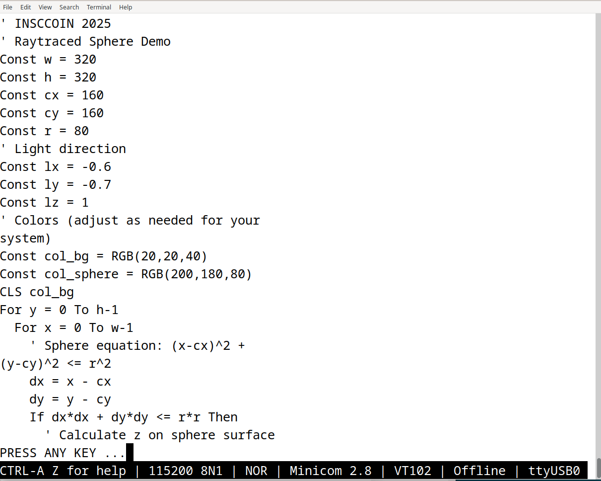
Each of these code samples is copied from the PicoCalc to a Debian Linux system, using the modem program, minicom, with settings of 115200 baud and 8-N-1. Then I typed list "g2.bas"

2 Likes

g3.bas

Could we draw an oscilloscope screen?

Sub draw_grid
  Local integer x,y
  dgrn = &H00AA00
  For y = 0 To 319 Step 80
    Line 0,y,319,y,,dgrn
  Next y
  Line 0,319,319,319,,dgrn
  For x = 0 To 319 Step 80
    Line x,0,x,319,,dgrn
  Next x
  Line 319,0,319,319,,dgrn
End Sub

Sub draw_sine
  For x = 1 To 318
    y = 160 + Int(Sin(x/10.0)*50)
    Pixel x,y,RGB(white)
    Next x
End Sub

draw_grid
draw_sine

For some of these programs, there are code lines that are longer than the PicoCalc screen will display. With the newer RC firmware, there is the new space-underscore line continuation syntax.

3 Likes

g4.bas

Drawing a pretend oscilloscope is fine, but wouldn’t it be better to plot some actual waveforms?

Sub draw_grid
  Local integer x,y,n
  'define a dark green
  dgrn = &H00AA00

  'horizontal lines
  For y = 0 To 300 Step 60
    Line 20,y,319,y,,dgrn
  Next y
  Line 20,300,319,300,,dgrn

  'vertical lines
  For x = 20 To 319 Step 60
    Line x,0,x,300,,dgrn
  Next x
  Line 319,0,319,300,,dgrn

  'scale, units
  For n = 0 To 4
     Text 0,(295 - n*60),Str$(n)+"V"
  Next n
  For n = 0 To 4
     Text (20 + n*60),310,Str$(n)+"s"
  Next n
End Sub

Sub draw_waveform
  'Make GPIO pin 28 into an analog input
  SetPin GP28, AIN
  For x = 21 To 318
    y = 300 - Int(Pin(GP28) * 60)
    Pixel x,y,RGB(white)
    Pause Int(1000 / 60)
  Next x
End Sub

Do
  draw_grid
  draw_waveform
  CLS
Loop

Because there’s just a short jumper wire plugged into GP28, the input floats and picks up noise. If I hold the PicoCalc close to my monitor screen, it increases. Away, it goes down. If I plug the GP28 wire into GND, it reads 0V. If I plug the wire into 3V3, the trace jumps up to 3.3V.

4 Likes

Note to everyone: This won’t work if you’re using an RP2350 (e.g. Raspberry Pi Pico 2) due to the GPIO bug which affects floating (and internally pulled-down) GPIO’s.

Edit: I didn’t read closely enough and should have realized that an ADC input was being used, which should not be affected under normal conditions.

2 Likes

Look at this raytraced sphere i did :slight_smile: pretty rad if you ask me.

' INSCCOIN 2025
' Raytraced Sphere Demo

Const w = 320
Const h = 320
Const cx = 160
Const cy = 160
Const r = 80

' Light direction
Const lx = -0.6
Const ly = -0.7
Const lz = 1

' Colors (adjust as needed for your system)
Const col_bg = RGB(20,20,40)
Const col_sphere = RGB(200,180,80)

CLS col_bg

For y = 0 To h-1
  For x = 0 To w-1
    ' Sphere equation: (x-cx)^2 + (y-cy)^2 <= r^2
    dx = x - cx
    dy = y - cy
    If dx*dx + dy*dy <= r*r Then
      ' Calculate z on sphere surface
      dz = Sqr(r*r - dx*dx - dy*dy)
      ' Surface normal
      nx = dx / r
      ny = dy / r
      nz = dz / r
      ' Lambertian shading
      dot = nx*lx + ny*ly + nz*lz
      If dot < 0 Then dot = 0
      ' Shade color
      shade = 40 + Int(180 * dot)
      If shade > 255 Then shade = 255
      If shade < 0 Then shade = 0
      c = RGB(shade, shade, Int(shade/2))
      Pixel x, y, c
    Else
      ' Background
      Pixel x, y, col_bg
    EndIf
  Next x
Next y

' Draw a ground shadow (simple ellipse)
For x = cx-r To cx+r
  For y = cy+r To cy+r+20
    dx = (x-cx)/r
    dy = (y-(cy+r))/20
    If dx*dx + dy*dy <= 1 Then
      c = RGB(30,30,30)
      Pixel x, y, c
    EndIf
  Next y
Next x

' Optional: Draw a highlight
For y = cy-r To cy+r
  For x = cx-r To cx+r
    dx = x - (cx-0.4*r)
    dy = y - (cy-0.5*r)
    If dx*dx + dy*dy < (0.1*r)^2 Then
      Pixel x, y, RGB(255,255,200)
    EndIf
  Next x
Next y

' Show text
Font 2
Text 60, 300, "Raytraced Sphere Demo"
Save image "sphere.bmp"
Pause 5000
CLS col_bg

2 Likes

Shouldn’t be the case as digital input should be turned off when analogue is enabled

2 Likes

My bad – I had a thinko and didn’t realize that an ADC rather than digital input was being used.

1 Like

What fun! What a cool image! Thank you, M57!

To transfer your code to the PicoCalc, I connected to my Linux desktop using a USB-C cable, and started minicom running at 115200 8N1 on serial port /dev/ttyUSB0 . The PicoCalc’s > prompt appeared.

Then I typed a XMODEM RECEIVE g5.bas on the PicoCalc’s keyboard, and in minicom on Linux, I typed a control-A, S, then selectedxmodem, and the path to your downloaded code file, which I’d named g5.bas .

A moment later, the file was on the PicoCalc and I could run it.

Now, I just have to struggle to understand the math again, after all these years.

(My intention with the posts in this thread, is just to share PicoCalc ideas, examples, and encouragement. Hopefully to help someone. Hopefully to learn some things, myself. )

2 Likes

@foobler these are really cool - now I can hardly wait for my PicoCalcs to arrive so that I can try them.

1 Like

Where are things like “OPTIONS GUI CONTROLS” documented? I’m looking in the PicoMite User Manual 6 and I can’t find that option, nor the rest of the GUI methods that you used here.

The program works fine on my PicoCalc, but I can’t find any documentation for some of the commands you used.

I think those functions are being depreciated. They are documented in the version 5 PicoMite manual.

The GUI controls are described in a “PicoMite Advanced Graphics” PDF, included in a PicoMite archive.

See comment:

Many of the widgets make sense for a touchscreen device, one of the design targets for MMBasic, I think.

MMBasic looks like it was made for a stand-alone boot-to-Basic computer, for a wifi device accessable online, and for touchscreen embedded controllers.

The PicoCalc is a bit different…

1 Like

Thank you so much! I can try my best to explain the math to you (I’m not a good teacher) I try to comment my code as much as I can because I’m quite forgetful myself.

1 Like