Internal i2C mounting (say 6 small modules). Either on platform above main board or on rear case. i2c running at highest "stable’ clock, maybe 20/40Khz (vs PicoCalc’s 10Khz).
Onboard DS3231 rtc with easy access lithium battery.
Onboard 8/16/32Mb permanent and fast FRAM via i2C.
Fastest possible LCD with touch panel (same resolution yet easy access display modes for speed or quality choices).
Gameboy style additional buttons.
Higher quality audio circuit with full 320Kbps mp3 and flac file playing. On board quality amp and 3.5mm headphone socket.
Better STM32 keyboard controller with ‘easy access’ ability to run user code alongside its main functions. Higher ‘stable’ i2C clock (say 20/40Khz vs 10Khz of PicoCalc).
…..
All quite possible with what is available today…. Your turn !
I don’t know what that board is you pictured, but I imagine I can’t get one from Amazon for $15 shipped and have it tomorrow. The main advantage of using a Pico/Pico 2 is they are common, cheap and you can get them anywhere. Plus, when the Pico 3 arrives, it will likely be pin compatible and a drop in replacement for a Pico/Pico 2. I’d stick with the Pico/Pico 2.
But I would like to see PSRAM that can actually be used with PicoMite Basic and an 8x10 matrix keyboard scanned directly by the Pico instead of this STM32 i2c hack they have going on here.
I’ve got the same (crazy) idea!
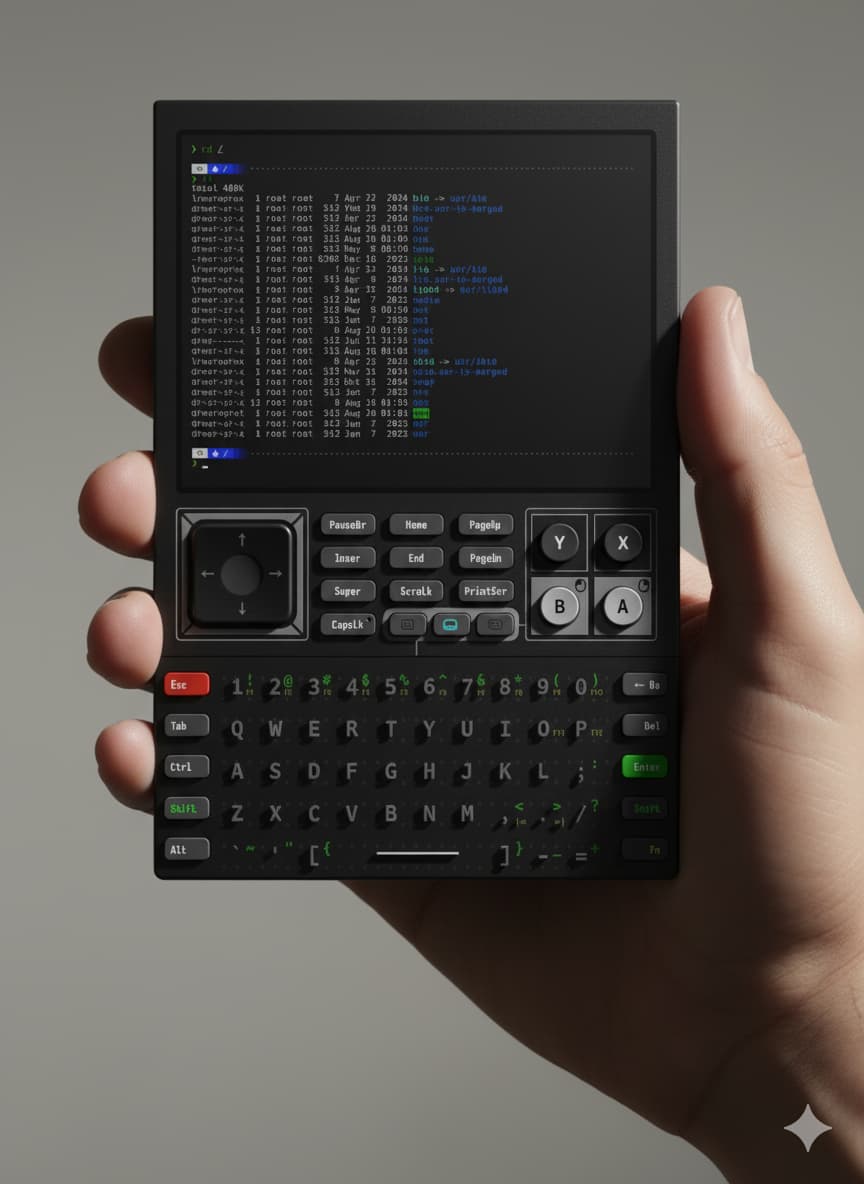
The design should be similar to the one Analogue used for their Pocket console.
The major bottleneck issue I’m facing now with the implementation is the interface with the pico… What should I use? QSPI? Hybride(SPI for instructions and parallel for datas)?
In fact, I wanted the GPU-HDL to be modular on the computer interface and the display (to handle multiple platform configuration, in this case QSPI (or else like I mentionned above) pico interface + parallel screen IO).
But for a first prototype, maybe I sould reduce the expectation to a simple SPI interface, as a PoC. And upgrade it later to something modular.
I would recommend using the conventionnal 100 kHz, this should ensure the compatibility over all the bus for every equipments you can find on the market!
And for the STM32, the STM32F4 series should do best than the F1 one. Can be used as an RTC too with cell battery on it and redesign of the power management.
Technically, the 100 kHz is from the I2C standard as the standard speed. 400 kHz for fast speed, 1 MHz fast plus speed, etc.
But at the same time, I had changed the frequency on both sides (Pico and STM32), and there were no issues. The path seems fine to me (even visually, there is nothing unusual about it).
I suppose the arduino-like lib in the official stm32 firmware mess up with the I2C timing. And I suppose CW team patch everything by reducing the I2C bus frequency.
So for me, 100 kHz or 400 kHz shouldn’t be an issue… Especially if we redesign the motherboard/picocalc like you suggest.
I forgot to mention that the big problem with FRAM is its architecture, which requires writing after reading. This can pose a significant risk of data corruption during operation if used as processing memory.
EDIT: From what I see on FRAM from infineon, the auto-write seem done inside the chip after a read from the user, and a ECC correct can correct 1 bit over 8 bytes in case of corruption. 2 bits errored aren’t corrected and only flagged in the status register.
I’m still curious to see the error counts per million reads.
Might be worth testing. But the largest capacity I can find is ~2 MB (16 Mbit).
At work, we replaced the EEPROM with FRAM to reduce power consumption. This was very useful!
Ok, ill play. Id like something like the Teensy 4.1 capabilities at Pico prices, Id also like at least 2 onboard DACs, and the ADCs able to keep up with higher clock speeds, a few times Iv overclocked just fine, until I tried the ADCs and had to back off the clock speed to get it working again. I`d also like 8 ports again like in the PIC chip and Atmega days.
Havent had a chance to look at this too closely, but the board-to-board pinout would need to be dealt with. There’s a schematic available so it might be easy for someone to redo the PCB layout/pinout and make it specific to the PicoCalc. If there’s interest I could get started in a few weeks, I’ve been too busy for something like this lately.
Interesting, shame it has only 4mb flash when some tout 16mb. Might be limiting in the future. Imagine MMBasic or other languages with much more wifi/bluetooth, Internet support ?. And where is the drop-in Pico3 ?.
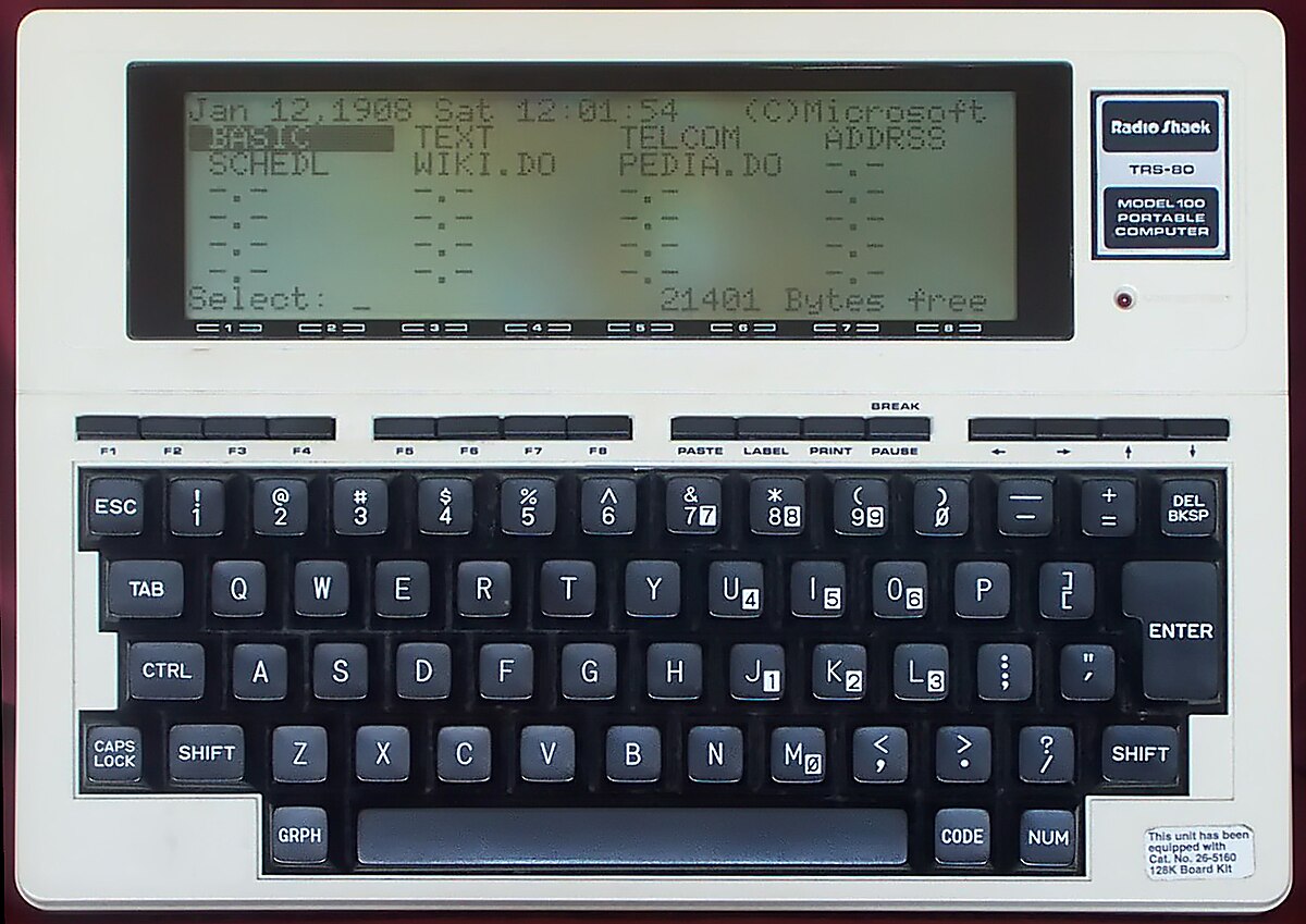
As my understanding,PicoCalc is trying to make something like comandore 64/ Apple 2 in your pocket.And Maybe PicoCalc 2 would be something Bring the Golden age of 90s back in the pocket
Hardware
7inch 4:3 VGA Screen;VGA/HDMI Interface 32bit color
A multitouch switchable touchpad&touchkeyboard provide “labor-saving” input experience like modern smartphones;
Also the touchpad can emulate 2 Analog Joystic when in Games;
3 x 18650 Battery module,can change to Lithium polymer battery;
A power saving x86 compute module,around Petium4 128M~256M RAM;(For those who want native ancient software)
Changable compute module,with 4GB + RAM;(For those who want modern software experience)
CF Card Storage;
Software:
Customized Linux with Retro OS Skin;(For those who desire a retro visual appearance, but are looking for accessible modern software)
Capacity to run OSs around 1990~2000;
Of course all DOS applications and Games,development environments etc;
Capacity to run those 4:3 aspect ratio console games with full speed and pixel perfect;