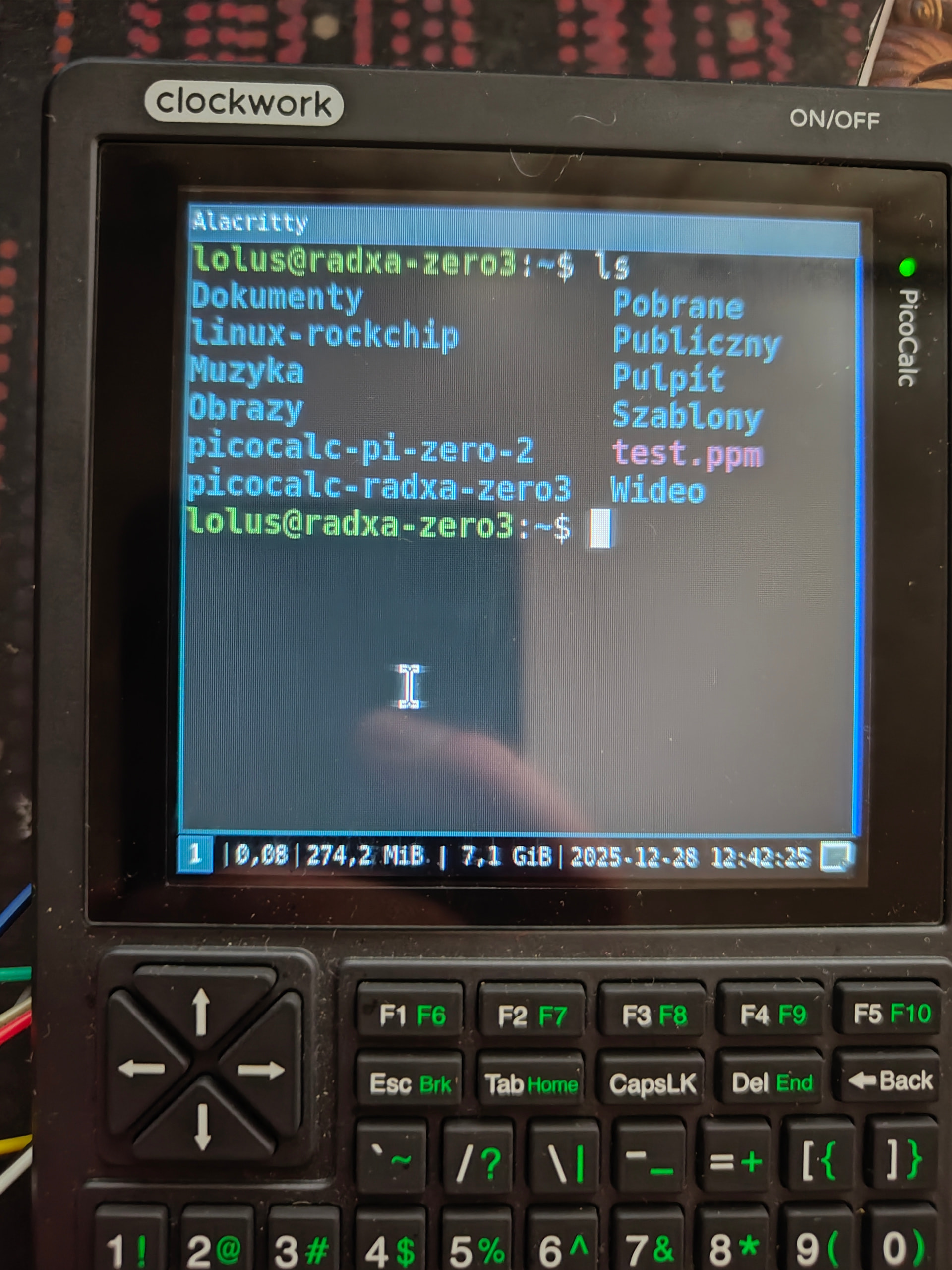
had to split it as I can attach only one at a time , below is a photo of the same screen after i sent a clear command

this looks strange and I do not understand what is happening here, any ideas ?
had to split it as I can attach only one at a time , below is a photo of the same screen after i sent a clear command
this looks strange and I do not understand what is happening here, any ideas ?
this dts file worked for a 2.2” Display for Radxa 3w
/dts-v1/;
/plugin/;

#include <dt-bindings/gpio/gpio.h>
#include <dt-bindings/pinctrl/rockchip.h>
#include <dt-bindings/interrupt-controller/irq.h>


/ {
        metadata {
                title = "Enable ILI9341 3.5inch RPi LCD (C) on SPI3-M1";
                compatible = "radxa,zero3";
                category = "display";
                exclusive = "GPIO4_C2", "GPIO4_C3", "GPIO4_C5", "GPIO4_C6", "GPIO3_A3", "GPIO3_C1" ;
                description = "Enable ILI9341 3.5inch RPi LCD (C) on SPI3-M1.";
        };
};


&spi3 {
        status = "okay";
        #address-cells = <1>;
        #size-cells = <0>;
        pinctrl-names = "default";
        pinctrl-0 = <&spi3m1_cs0 &spi3m1_pins>;
        max-freq = <32000000>;
        fbili9341:ili9341@0 {
                compatible = "fbtft,ili9341";
                reg = <0>;
                spi-max-frequency = <4000000>;
                rotate = <0>;
                bgr;
                fps = <30>;
                buswidth = <8>;
                reset-gpios = <&gpio3 RK_PC1 GPIO_ACTIVE_LOW>;
                dc-gpios = <&gpio3 RK_PA3 GPIO_ACTIVE_HIGH>;
                debug = <0>;
                init = <0x1000001
                        0x20000E8
                        0x1000011
                        0x20000E8
                        0x100003A 0x55
                        0x20000E8
                        0x1000036 0x08
                        0x20000E8
                        0x1000029>;

        };

};
this is how the build came out! It looks so much better than i expected, and i really love the transparent look. I’m going to experiment with active cooling, because the pi can get quite hot! When i have a solution i will share it with you guys!
THANK YOU!
got it to work using fbtft
ill get my setup/scripts on github, gimme some time.
wonder why the mipi-dbi-spi did not work, here is DTS for anyone interested before I get setup script on the hub
/dts-v1/;
/plugin/;


&spi3 {
        status = "okay";
        #address-cells = <1>;
        #size-cells = <0>;
        pinctrl-names = "default";
        pinctrl-0 = <&spi3m1_cs0 &spi3m1_pins>;
        max-freq = <50000000>;
        fbili9341:ili9341@0 {
                compatible = "fbtft,ili9341";
                reg = <0>;
                spi-max-frequency = <50000000>;
                rotate = <0>;
                bgr;
                fps = <30>;
                buswidth = <8>;
                regwidth = <8>;
                height = <320>;
                width = <320>;
                reset-gpios = <&gpio3 17 1>;
                dc-gpios = <&gpio3 10 0>;
                debug = <0>;
                init = <
                        0x10000b0 0x00 //interface mode control
                        0x1000011 //sleep out command
                        0x20000ff //no idea what this does
                        0x100003a 0x55 //pixel format. DBI=DPI=16bits per pixel (from ili9341 init)
                        0x10000F7 0xA9 0x51 0x2C 0x82 //adjust control 3
                        0x10000C0 0x11 0x09 //power control 1
                        0x10000C1 0x41 //power control 2
                        0x10000C5 0x00 0x0A 0x80 //voltage common control
                        0x10000B1 0xB0 0x11 //frame rate control
                        0x10000B4 0x02 //display inversion control
                        0x10000B6 0x02 0x02 //display function control (2nd param SS shift direction was 0x22 from arduino code)
                        0x10000B7 0xC6 //entry mode set
                        0x10000BE 0x00 0x04 //HS lanes control
                        0x10000E9 0x00 //set image function
                        0x1000036 0x08 //memory access control
                        0x1000021
                        0x10000E0 0x00 0x07 0x10 0x09 0x17 0x0B 0x41 0x89 0x4B 0x0A 0x0C 0x0E 0x18 0x1B 0x0F //PGAMCTR positive gamma control
                        0x10000E1 0x00 0x17 0x1A 0x04 0x0E 0x06 0x2F 0x45 0x43 0x02 0x0A 0x09 0x32 0x36 0x0F //NGAMCTRL negative gamma control
                        0x1000011 //sleep out command
                        0x1000029>; //display on
          };

};
the case looks beautiful! Are the dimensions working in resin?
How you are doing with the heat of the rockchip, It was getting really hot on my side with a high load. (80 °c)
I am yet to tackle this, my plan is to under-volt / under-clock it a bit, also there is a little bit of space for a heat sink
I used the 4 or 5 mm Heatsink with acceptable result. Or you may use a thinner one with a fan.
Yes! The port for the usb port is a bit loose, but with widening up the clips on the usb port I got it to fit nicely!
Same for me. I stuck a heatsink on the cpu, but it gets heatsoaked within 20 mins. I am going to try to use a argon thrml for the raspberry pi 5 to fit into the case
I wonder about the battery life too!
But it looks awesome! that and the pins can make wonder for DIY projects I guess!
also, how much ram your radxa has if I can ask :)?
well, not realli able to answer at the moment but when trying to make it work, it lasted a few hours on a somewhat good used 3000mAh 18650 from a vape. it is an 8GB version with no emmc. I am now making a bard to mount it inside, then will test it
There is space for a heatsink, but a underclock isn’t that useful, because the raspberry pi zero is already on the slow side for a desktop os
the battery life really depends on what you’re doing with it. when it is sitting at idle and doing nothing, it doesn’t consume anything, but when i’m gaming, it does drain my double 3500 mah cells fast enough that it is empty within 4 hours
that is why I am using radxa zero 3, it is way more powerful, just looking at the clocks it is 1.8x and has 4 cores, they are also newer/better cores. thus under-voliting / under-clocking it by a 100-500 mhz is not that bad of an option.
I did a run of glxgears, as a medium stress test and it hit almost 80 deg C while holding 1.4-1.8 GHZ
while idle it has 40-50 deg C depending if it is vertical or laying down
with that result I am not sure if i will even put a heat sink on it as i would have to buy one and I am cheap
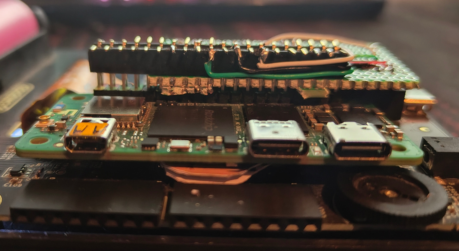
I am assuming that underclocking to 1.1 would keep temperature lower than 50C. How you aded the radxa to the pico? I am assuming you soldered a board on top as an interface between the pin holes for the original pico and then over the soldered one you have the inputs for the radxa one? I am almost getting one if I can see how everything can fit together nicely ![]()
to make Radxa fit in to the Calc I committed war crimes against common sense and engineering…
I am making a git repo that will have setup scripts for everything GitHub - L0lus/PicoCalc-Radxa-zero-3: Radxa Zero 3 on Picocalc not ready yet but will be in a few hours if everything goes well
undervolting would decrease the voltage (and potentially make SoC less stable) which would make SoC draw less current and heat up less while performance stays the same but SoC stays cooler and draws less power
underclocking achieves same thing but decreases performance, so if I can get away without underclocking I would be happy
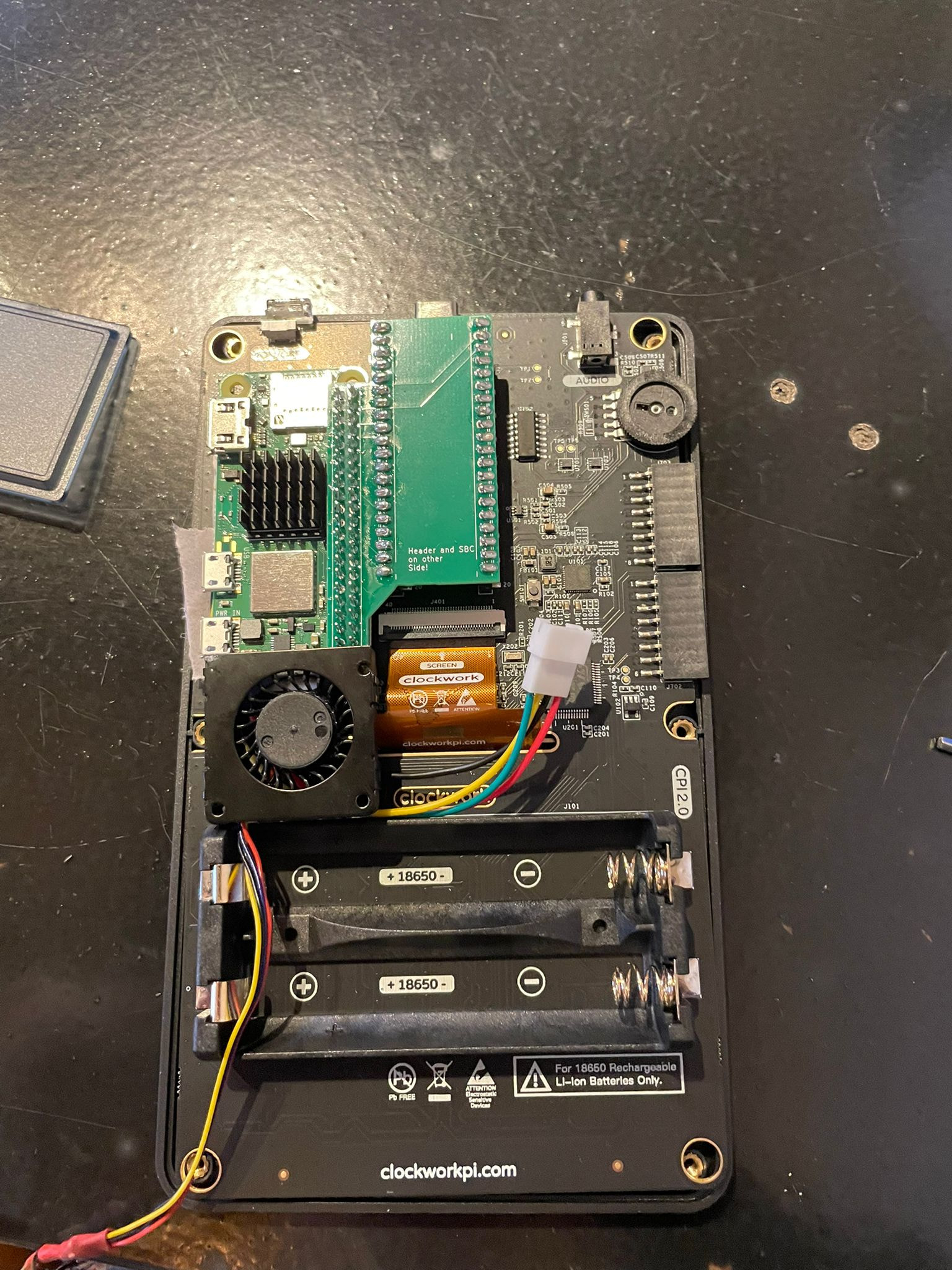
what I did:
the result is an unmodified case and unmodified Radxa board that I can later reuse
i think that i’ve found the solution for radxa and raspberry pi sbc’s. I used a 30 mm blower fan off a raspberry pi 5 heatsink, specifically from an argon thrml heatsink (link below). i haven’t tested it yet, because i’m on vacation and i don’t have any off my soldering stuff with me unfortunately, but the it fits perfectly between the raspberry pi and the battery holders. I will look into a mounting mechanism, but for now i will stick it to the camera port with some double sided tape. I will also need to modify the case for the hot air to exit. I will look into everything later this week when i’m back at home again!
I mean, if t works, it works…