the spi interface that pico calc now using have no enough speed to drive such high resolution screen,often this kind of screen would use mipi or HDMI for better refresh rate and color depth。
1 Like
Pinout and interface is completely different, so it’s not usable without a completely redesigned mainboard.
2 Likes
That display is used on this product - HackberryPi_Zero with BBQ20 keyboard
1 Like
I made a prototype PicoCalc relay board for RasPiZeroW2, and while enjoying Raspbian with PicoCalc, I noticed a few things. These things may be trivial, but I’d like to leave a few notes.

The RasPiZero-PicoCalc relay board I made has two possible power supply methods.
a). One of them is PicoClac VSYS–>RasPiZero GPIO 5Vpin
b). The other is PicoClac VSYS–>5V boost module–>RasPiZero GPIO 5Vpin
I tried this with adafruit PowerBoost1000 Basic.
In the case of a)., it seems that the voltage of the LiPO battery is supplied to the RasPiZero.
In other words, it does not reach 5V, but the RasPiZero generates 3.3V etc. internally, so it will work.
When connecting a USB device to the USB on the side of the RasPiZero, the USB data line is not 5V, and most USB devices generate 3.3V etc. from the power supplied by the USB, so many will work.
However, as the voltage of the LiPO battery drops, the connected USB device may stop working even though the RasPiZero2W is working.
This is not surprising when you think about the inside of the RasPiZero2W, but it is a big problem for the connected USB device.
Specifically, if a USB memory or USB SD card slot is connected to the RasPiZero2W, the voltage drop of the LiPO battery may cause the mount to suddenly be released, and this has actually happened.
This should be avoided as it can cause serious damage to the USB memory or SD card. To avoid this, you need to be careful of the voltage drop of the LiPO battery.
If it drops below 3.7V, it’s probably dangerous.
In the case of b), the 5V boost module supplies 5V to the RasPiZero2W, making the above less likely to occur.
The 5V boost module is a hard worker that outputs 5V even if the LiPO voltage drops to a certain extent, but this can cause problems.
For example, when the LiPO voltage dropped significantly, the PicoCalc keyboard became inoperable.
The keyboard is controlled by the STM32, but looking at the firmware, it seems that there is a description that shuts down when the LiPO battery voltage drops significantly.
I was unable to confirm whether that event occurred or if there was another cause, but I learned that I should pay attention to the LiPO battery voltage.
The adafruit PowerBoost 1000 Basic lights up a red warning LED when the voltage is 3.2V, but this warning may be too late for PicoCalc.
This has been a bit of a long story, but in short, it seems that the things you need to be careful of are as follows:
-To save power, disable WiFi/Blutooth when not in use
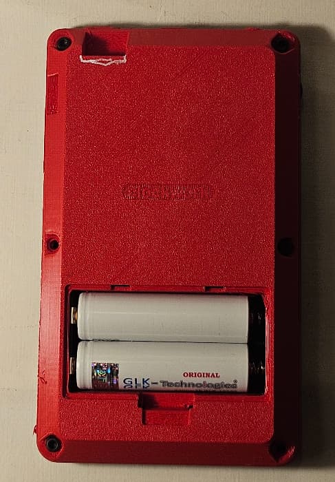
-To avoid sudden drops in voltage, install two LiPO batteries
-Make sure the LED in the upper right corner of the PicoCalc screen is not yellow
-Before connecting a USB device to the RasPiZero2W, try a quick check of the LiPO battery voltage with [Alt]+[b]
Thanks for reading.
6 Likes
Where would i find the case stl for this ? I see only a cover
Back panel data can be found here.
1 Like
Thank you very much, for all the optioins
1 Like
I’m super excited to try this out
Hi, I will try it your way, because having access to hdmi port would be really nice. Of course I have to adapt the backpanel.
I have ordered it now. My first PCB.

[EDIT]
Working on a new case for the addon PCB. Should have a access to sdcard and also hdmi.

7 Likes
Hi,
What about a power booster with more than one amphere?
A soon I receive my PCB i will give it a shot. A maybe have to cut some traces ![]() , I have forgot the power booster pins.
, I have forgot the power booster pins.
Hello.
I haven’t tried a PowerBooster that outputs more than 1A.
This is because the Raspberry Pi Zero 2W consumes about 5V 120mA for light loads and about 500mA for heavy loads.
I was also planning to connect USB devices that don’t consume much power, such as an SD card reader and USB memory stick.
In other words, I expected that about 1A would be sufficient for all of them combined.
There are probably many PowerBoosters that can output more than 1A.
For example,
suggests using the 5V Step-Up Voltage Regulator U3V40F5.
You’ll probably find many such PowerBoosters if you search.
I hope your project goes well.
1 Like
Thanks for the heads up. I will try this booster module. PBC Arrived today, something to do on the weekend.
2 Likes
Hi,
Success!
@wasdwasd0105 Thank you for your work!! All Features are working.


I will release the Gerber files later.
Case need some work:

Blank back, maybe a removeable door again .. ?
BTW: Original case also still fits.
4 Likes
Love your design, looking forward to the release.
1 Like
Can you use RaspiOS Bookworm for this?
I think wasdwasd0105 scripts only works with bulleye.
I have not tested Bookworm.
Hi,
Here are the Gerber Files.
4 Likes
If some one is interested, a build video:
6 Likes
around how many people use the PicoCalc with the Pi zero in it?
1 Like