I got uconsole with radxa cm5 to boot under the bookworm image with the rtl sdr aio board attached from when the system was power off. It was done by physically blocking the original uart1 connection from rpi (TXD1, RXD1, RTS1, CTS1). To do so, apply insulating tape strips to the male side of mini pcie connector, at the 3rd and 6th pins on the odd number side, and 5th and 6th on the even number side (the numbers of pins for the mini pcie connector can be checked on the schematic of mainboard in the uconsole Github repo. I quick tested the usb hubs on the board that worked.
Can you make a easy guide with pictures how to do it I have a spare v1 laying around and would be cool to get it working.
Of course.


As shown in the picture, those pins pointed out with red arrows and covered in orange (which is the Polyimide insulating tapes. Just cut out insulating tapes (I was using Polyimide tapes, but any insulating tape that is reasonably thin and adhering well on the surface of copper should work) in 1mm wide for a single pin, or 2 mm for two continuous ones. I am still working on it, though my current focus is to get my wifi card work on the radxa CM5. The pinouts of other functions like RTC, SDR and Lora may be tested two days later.
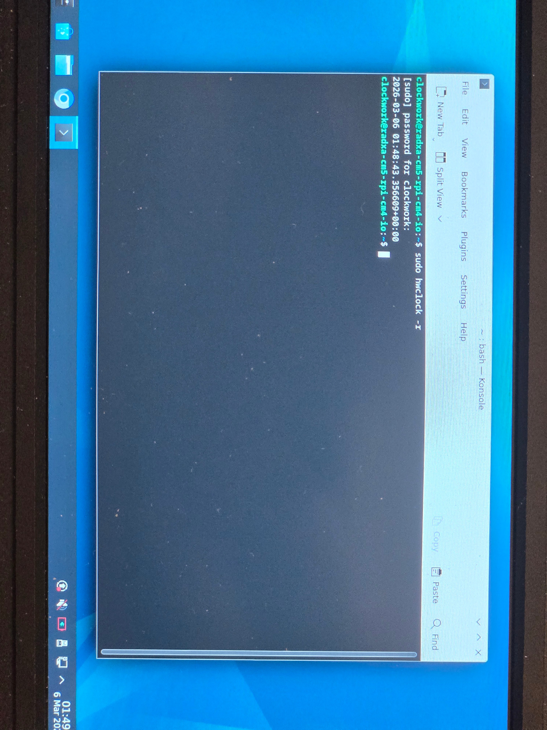
The RTC seemed to work right away with the aio board inserted and the RTC battery attached to the AIO board. Function of RTC can be checked to command below:
sudo hwclock -r
It should be similar to the output given in the official guideline by HG.
I assume that the RTC function is supported by the PCF85063A chip on AIO board rather than the intrinsic function of Radxa CM5, which may require the adapter board by HG with the RTC battery connector, though I’m not sure lol.
I have compiled an u-boot that set CONFIG_BOOTDELAY=-2, which tells u-boot to ignore interrupts from UART2 except for Ctrl+C during u-boot. I tested it on uconsole mainboard, and it did boot successfully when hackergadgets AIO board V1 was installed. However, it messed uo with poweroff. To be specific, logs in kernel suggested a regular poweroff in kernel. Power indicator on Radxa CM5 was off, suggesting that CM5 had no power. After pressing power button for 15s, instead of shutting off the green light, the greenlight kept blinking at lower brightness once to twice in one second. Further pressing power button for long did make the power light shine constantly brightly, but CM5 showed no indication of powered on. If battery was removed during dimmer blinking period and installed backon, the CM5 seemed kept from loading kernel during booting. Such state ended after booting CM5 normally with no UART2 input disrupting, which will tolerate HG AIO V1 installed. It is a totally uncharted area to me in terms of power supply on the mainboard.