Would this board work in our Uconsoles?
it
is
a
mistery
1 Like
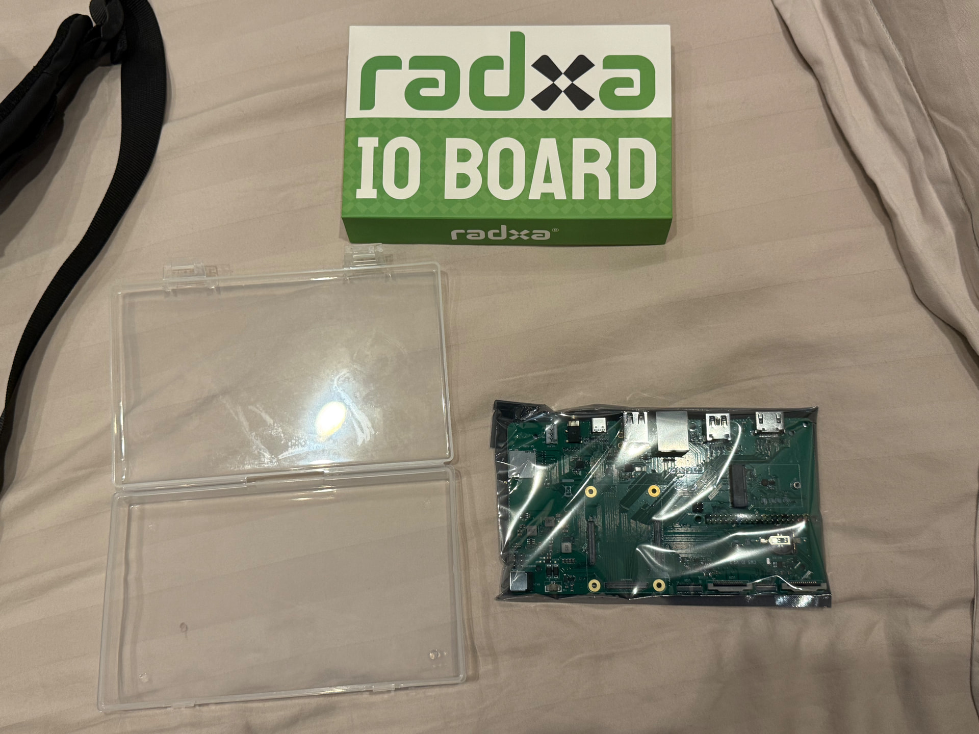
@white-round-square Thank you!!
I’ll get one and give it a go lol.
1 Like
AFAIK there is no wifi on radxa so you need to use an usb adapter
What the hell!
I won’t bother…
1 Like
Haha! The Radxa CM5 is certainly interesting in a uConsole, but not so practical, and for more reasons than just the WiFi.
The ClockworkPi mainboard has its own WLAN interface, doesn’t it? It allows the CM3 to use WiFi:
Configuration would be non-trivial and I don’t have a system to test, but with some device tree magic couldn’t it be used from the Radxa?
The main board Wi-Fi is not physically connected to the CM through the adapter board.
1 Like
I didn’t understand how you got your information so I found it for myself:
I’ll be referencing the ClockworkPi mainboard schematic and the CM4 adapter board schematic. Ranges are inclusive of the start and end.
On the mainboard, the WLAN subsystem uses the GPIO pins 3-7 for basic configuration, 14-17 for UART, 18-21 for PCM, and 22-27 for SDIO. These are all wired to the SODIMM connector for the core modules. The adapter board wires the SODIMM pins to the CM4 pins like so:
- SODIMM GPIO3-5 → CM4 GPIO3-5
- SODIMM GPIO6-7 → floating
- SODIMM GPIO14-27 → floating
So the best one can do with the CM4 adapter board is mess with the enabled state of some of the radio components on the mainboard, and one would need a new adapter board to use the mainboard’s radios.
I remain unsure of the significance of the gpio35-39 from the overlay name. It would make some sense that the mentioned pins 35-39 were physical pins on the Pi 3, corresponding to Broadcom GPIO numbers (on the schematics) 19 (PCM_SYNC), 16 (UART_RTS_N), 26 (SDIO_D_2), 20 (PCM_OUT), and ground, respectively, but then that looks like a garbled mess of signal lines.
2 Likes
the numbers are for the BCM GPIOs, not the physical pins on the pi connector
1 Like
Could you be more verbose? I don’t know to which numbers you are referring.
It’s BCM (Broadcom) gpio 35 to 39 not physical pins 35 to 39 on the 40 pin connector
All pin numbers in the overlays are Broadcom pins
1 Like
Do you know what the significance is of those GPIOs with regards to the WLAN subsystem?
those pins can be SPI pins, so they can be used for SDIO which is what the wifi chip uses
Do you know where those GPIOs are connected, electrically, to the WLAN subsystem? Perhaps I am misreading the schematic.

What do we do about the audio?
bluetooth headphones/speaker?