UF2 Loader release

The SDBoot/multi_booter bootloader that @adwuard and @guu amongst others have done a bunch of work on is fantastic but it has a couple of glaring limitations that I couldn’t tolerate:

  1. It requires recompiling every application with a custom linker script
  2. It only reads .bin files instead of the usual .uf2 format, so various platform safety features are lost

UF2 Loader is a reworked version of the bootloader that fixes these two issues. Just stick (almost) any uf2 file you like onto the SD card, and this loader can use it directly.

If an application is loaded, it will automatically boot unless UP, F1 or F5 is held during power on. The first entry in the file list (shown in square brackets) will show the filename of the loaded application if one is present, and will boot to it directly without reflashing if selected.

Holding DOWN or F3 during power-on instead will put the Pico into BOOTSEL mode if you need it.

There is also a simple diagnostic tool in case you can’t successfully get the menu to appear - it checks that the SD card can be successfully mounted and the BOOTnnnn.UF2 file is present and can be read.

To install uf2loader you need to flash the appropriate bootloader.uf2 for your pico model in bootsel mode, copy both BOOT*.UF2 files to the root of your sd card, make pico1-apps and pico2-apps folders on the sd card, and stick your desired applications in those folders.

11 Likes

a couple of quick questions:

  1. “top of flash” means highest address, correct? So our boot stage2 directly goes to “high mem” and only drops back to prog_info->addr if booting in normal mode?
    • apps like picomite writes to flash and not aware of the loader, potential overwrite?
  2. for pico2, I skimmed through the datasheet (thanks for the link) section 5 – what’s the plan? re-compile everything to target a higher address and then translate? why can’t we just use the default, 2040-like behavior?
  3. any change that we support data restore? (dump/restore all flash minus the range specified in the uf2)

Fantacy !
Will it be better to make the boot menu show every time bootup but auto-select the last firmware after a short timeout like GRUB or Windows Bootloader do on a PC? PicoCalc boot very fast,1~2 second time out wouldn’t make a different but will make the select operate more easy (clicking one button is easyer than hold down 2 buttons every time when boot up)

If the program tries to overwrite the bootloader it will succeed, yes. So don’t do that. Unfortunately the RP2040 doesn’t have a means of write protecting sections of flash.

As far as PicoMite goes, just stay in the first flash slot, at least for now. But really you should use the SD card for storage.

The RP2350 has a completely redesigned boot system, it doesn’t execute boot2 in the way that the RP2040 does. So it can’t work. But the added capabilities it has means there is a much nicer way to do the same thing, with the application living in its own partitioned space.

Autobooting into the application wasn’t my original choice, it’s what multibooter does. But I’m increasingly coming around to it. Most of the time you won’t be changing application every time you turn on the unit. And holding down a key when you want to do so is pretty straightforward. If it’s really bothersome, it’s trivial to compile a custom version.

Even if the user doesn’t decide to use any of the flash slots in PicoMite, it will save a certain amount of data to flash. That’s how it stores the OPTION values, but it also stores whatever MMBasic file you last loaded in the editor to flash, and possibly some other things. The 3 flash slots also seem to be regularly used by people. At the very least, one of them is useful to use AUTORUN to run some code at power on. But some people use them to store libraries and such.

So if there’s no provision for preventing PicoMite from overwriting the bootloader, then it’s probably wise to just suggest no one uses it with PicoMite. The existing multibootloader patched PicoMite to shift where the flash data was stored. So that might work here too.

It would be nice if PicoMite’s flash area could be saved and loaded to SD as needed between boots (and ideally any firmware’s custom flash area if it has one), but if that’s not possible, it’s probably dangerous to just let PicoMite write into sensitive areas of flash and clobber the bootloader. (And I’m pretty sure it will!) Hopefully that wouldn’t brick the pico and the “nuke” firmware could be used to wipe it so it could be used again.

There’s actually no risk of PicoMite overwriting anything, as it doesn’t come close to using all of the available flash. Options are saved in a 20k block at 832k offset, immediately followed by the three flash slots of 128k each, and then the optional module buffer which is at most 512k. That leaves a guard region of 164k before getting to the bootloader.

Saying “nobody should use this with PicoMite” seems a tad extreme.

Also, the job of saving/restoring those flash slots to SD falls entirely on PicoMite itself.

1 Like

Sounds good. I didn’t realize there was enough space already for it all.

This made it sound like PicoMite could easily overwrite the bootloader. Hence my post.

It’s fine, it forced me to actually figure out the full details instead of just handwaving it. :smiley:

1 Like

I’ve made a v1.1 release with the magic number for bootloader detection added. If XIP_BASE+0x1ffff8 is 0xe98cc638 then XIP_BASE+0x1ffffc can be trusted to be the bootloader start address, and all addresses below that are safe for an application to write to.

(as of v2.0 the magic number is at XIP_BASE+0x110 and the flash size is at XIP_BASE+0x114)

1 Like

I could be missing something. That is 2MB in, what happens on the Pico 2 with 4MB of flash, or other boards with more? How large is the boot loader, is it just a single 4k flash sector that needs to be respected?

The bit you’re missing is that the Pico 2 isn’t currently supported. However when it is, it won’t need this scheme since the application will be properly partitioned away from the bootloader.

For RP2040 boards with different amounts of flash, both the bootloader and the applications would need to be recompiled anyway. This is another reason why I specifically say Pico 1 instead of RP2040.

And I wish the bootloader was 4k! It’s a full GUI application with filesystem support, it’s actually about 140k right now, and that’s using MinSizeRel and nanolib.

2 Likes

Ok, got it! It sound like the Pico 2 will be much cleaner.

Remember for the PicoMite/WebMite the firmware uses all flash above the flash slots/modbuffer as the A: drive using LittleFS. It automatically sizes the A: drive to the size of the actual flash chip.
In addition new releases that have any significant changes typically re-write all flash.

1 Like

It’s done a poor job of wiping the bootloader on my unit so far… :smiley:

I don’t think LittleFS actively wipes flash unless it needs the space (and I’d be extremely suspicious of it’s implementation if it did.) All it needs to do is clear it’s directory metadata.

But point taken. It’s a good opportunity to write a standard implementation of my flash size check.

To clear it up: with pico2+partition+address translation, there’s no risk of overwriting, right?
Writing outside the partition should cause a bus fault.

Another question: could we initialize SPI and load sdboot from sdcard instead (no filesystem, just follow some convention and read a consecutive block at an offset)?

What’s the size limit of stage2?

Boot stage 2 has to be exactly 256 bytes, and it’s packed to the gills already. I don’t see anything else fitting in there!

…would have been a neat trick, though.

Edit: it just occurred to me that an alternative would be to turn the bootloader into a minimal stage3 that can either launch the application or load one into RAM from the SD card. Since there’s no real need for the UI unless the SD card is present. The UI would just be a PICO_NO_FLASH application. Hmmm.

I’ve got a working generic routine for determining the safe application space on an RP2040. I put this into PicoMite and it’s successfully limiting it’s A drive to below the bootloader.

deleted as protocol has changed with v2.0

2 Likes

that’s exactly what I meant. 256byte stage2 does nothing other than chainloading stage3.
Stage3 by default boots into FLASH app, and only loads the UI, FAT driver etc. when entering an alt mode.

I asked AI to re-write stage2 to load 4KB stage3 into RAM:

// ----------------------------------------------------------------------------
// Second stage boot code - microSD variant
// Copyright (c) 2025 Custom Implementation
// SPDX-License-Identifier: BSD-3-Clause
//
// Device:      microSD card via SPI
//
// Description: Configures SPI interface to communicate with microSD card,
//              loads stage3 bootloader from fixed offset (1MB) into SRAM,
//              then jumps to stage3 for further initialization.
//
// Details:     * Initialize SPI interface for microSD communication
//              * Send CMD0, CMD8, ACMD41 to initialize SD card
//              * Read stage3 from sector 2048 (1MB offset) into SRAM
//              * Jump to stage3 in SRAM
//
// Building:    * This code must be position-independent, and use stack only
//              * The code will be padded to a size of 256 bytes, including a
//                4-byte checksum. Therefore code size cannot exceed 252 bytes.
// ----------------------------------------------------------------------------

#include "pico/asm_helper.S"
#include "hardware/regs/addressmap.h"
#include "hardware/regs/spi.h"
#include "hardware/regs/pads_bank0.h"
#include "hardware/regs/io_bank0.h"
#include "hardware/regs/resets.h"

// ----------------------------------------------------------------------------
// Config section
// ----------------------------------------------------------------------------

// SPI pins for microSD (using SPI0)
#define SD_CLK_PIN  18
#define SD_MOSI_PIN 19  
#define SD_MISO_PIN 16
#define SD_CS_PIN   17

// SPI clock divider (400kHz for init, will switch to faster later)
#define SPI_CLKDIV_INIT 312  // 125MHz / 312 ≈ 400kHz
#define SPI_CLKDIV_FAST 4    // 125MHz / 4 = 31.25MHz

// Stage3 parameters
#define STAGE3_SECTOR   2048    // 1MB offset (512 * 2048)
#define STAGE3_SIZE     8192    // 4KB stage3 size
#define STAGE3_LOAD_ADDR 0x20010000  // Load into SRAM

// SD commands
#define CMD0    0x40
#define CMD8    0x48
#define CMD55   0x77
#define ACMD41  0x69
#define CMD17   0x51

// ----------------------------------------------------------------------------
// Start of 2nd Stage Boot Code
// ----------------------------------------------------------------------------

pico_default_asm_setup

.section .text

regular_func _stage2_boot
    push {lr}
    
    // Enable SPI0 and IO_BANK0 in reset controller
    ldr r3, =RESETS_BASE
    ldr r0, =(RESETS_RESET_SPI0_BITS | RESETS_RESET_IO_BANK0_BITS | RESETS_RESET_PADS_BANK0_BITS)
    ldr r1, [r3, #RESETS_RESET_OFFSET]
    bics r1, r0
    str r1, [r3, #RESETS_RESET_OFFSET]

    // Wait for reset done
1:  ldr r1, [r3, #RESETS_RESET_DONE_OFFSET]
    tst r1, r0
    bne 1b

    // Configure GPIO pins for SPI
    ldr r3, =IO_BANK0_BASE
    
    // CLK pin
    movs r0, #5  // SPI0 SCK function
    str r0, [r3, #(IO_BANK0_GPIO0_CTRL_OFFSET + SD_CLK_PIN * 8)]
    
    // MOSI pin  
    str r0, [r3, #(IO_BANK0_GPIO0_CTRL_OFFSET + SD_MOSI_PIN * 8)]
    
    // MISO pin
    str r0, [r3, #(IO_BANK0_GPIO0_CTRL_OFFSET + SD_MISO_PIN * 8)]
    
    // CS pin as GPIO output
    movs r0, #5  // SIO function
    str r0, [r3, #(IO_BANK0_GPIO0_CTRL_OFFSET + SD_CS_PIN * 8)]

    // Set CS high initially
    ldr r3, =SIO_BASE
    movs r0, #(1 << SD_CS_PIN)
    str r0, [r3, #SIO_GPIO_OUT_SET_OFFSET]
    str r0, [r3, #SIO_GPIO_OE_SET_OFFSET]

    // Configure SPI0
    ldr r3, =SPI0_BASE
    
    // Disable SPI
    movs r0, #0
    str r0, [r3, #SPI_SSPCR1_OFFSET]
    
    // Set clock rate for initialization
    movs r0, #SPI_CLKDIV_INIT
    str r0, [r3, #SPI_SSPCPSR_OFFSET]
    
    // Configure SPI: 8-bit, SPI mode 0
    movs r0, #7  // 8-bit data
    str r0, [r3, #SPI_SSPCR0_OFFSET]
    
    // Enable SPI
    movs r0, #SPI_SSPCR1_SSE_BITS
    str r0, [r3, #SPI_SSPCR1_OFFSET]

    // Send 80 clock cycles with CS high (SD card initialization)
    movs r2, #10
init_clocks:
    movs r0, #0xFF
    bl spi_write_byte
    subs r2, #1
    bne init_clocks

    // Assert CS low
    ldr r1, =SIO_BASE
    movs r0, #(1 << SD_CS_PIN)
    str r0, [r1, #SIO_GPIO_OUT_CLR_OFFSET]

    // Send CMD0 (GO_IDLE_STATE)
    movs r0, #CMD0
    bl send_sd_cmd
    movs r1, #0
    movs r2, #0
    bl send_sd_args
    bl get_sd_response
    
    // Send CMD8 (SEND_IF_COND) 
    movs r0, #CMD8
    bl send_sd_cmd
    ldr r1, =0x1AA
    movs r2, #0
    bl send_sd_args
    bl get_sd_response

    // Send ACMD41 (SD_SEND_OP_COND) - loop until ready
acmd41_loop:
    // First send CMD55
    movs r0, #CMD55
    bl send_sd_cmd
    movs r1, #0
    movs r2, #0
    bl send_sd_args
    bl get_sd_response
    
    // Then send ACMD41
    movs r0, #ACMD41
    bl send_sd_cmd
    ldr r1, =0x40000000
    movs r2, #0
    bl send_sd_args
    bl get_sd_response
    
    // Check if ready (bit 7 of response)
    movs r1, #0x80
    tst r0, r1
    beq acmd41_loop

    // Switch to faster clock
    movs r0, #SPI_CLKDIV_FAST
    str r0, [r3, #SPI_SSPCPSR_OFFSET]

    // Read stage3 from sector 2048
    ldr r4, =STAGE3_LOAD_ADDR
    ldr r5, =STAGE3_SECTOR
    
read_stage3:
    // Send CMD17 (READ_SINGLE_BLOCK)
    movs r0, #CMD17
    bl send_sd_cmd
    mov r1, r5
    lsls r1, #9  // Convert sector to byte address
    movs r2, #0
    bl send_sd_args
    bl get_sd_response
    
    // Wait for data token (0xFE)
wait_data_token:
    bl spi_read_byte
    cmp r0, #0xFE
    bne wait_data_token
    
    // Read 512 bytes
    movs r2, #512
read_sector_loop:
    bl spi_read_byte
    strb r0, [r4]
    adds r4, #1
    subs r2, #1
    bne read_sector_loop
    
    // Read CRC (2 bytes, ignore)
    bl spi_read_byte
    bl spi_read_byte
    
    // Read next sectors if needed
    adds r5, #1
    ldr r0, =(STAGE3_SIZE / 512)
    cmp r5, r0
    blt read_stage3

    // Deassert CS
    ldr r1, =SIO_BASE
    movs r0, #(1 << SD_CS_PIN)
    str r0, [r1, #SIO_GPIO_OUT_SET_OFFSET]

    // Jump to stage3
    ldr r0, =STAGE3_LOAD_ADDR
    bx r0

// Helper functions (ultra-compact versions due to space constraints)
spi_write_byte:
    ldr r1, =SPI0_BASE
    str r0, [r1, #SPI_SSPDR_OFFSET]
1:  ldr r2, [r1, #SPI_SSPSR_OFFSET]
    movs r3, #SPI_SSPSR_BSY_BITS
    tst r2, r3
    bne 1b
    ldr r0, [r1, #SPI_SSPDR_OFFSET]
    bx lr

spi_read_byte:
    movs r0, #0xFF
    b spi_write_byte

send_sd_cmd:
    push {lr}
    bl spi_write_byte
    pop {pc}

send_sd_args:
    push {lr}
    lsrs r0, r1, #24
    bl spi_write_byte
    lsrs r0, r1, #16
    bl spi_write_byte
    lsrs r0, r1, #8
    bl spi_write_byte
    mov r0, r1
    bl spi_write_byte
    movs r0, #0x95  // CRC for CMD0/CMD8
    bl spi_write_byte
    pop {pc}

get_sd_response:
    push {lr}
    movs r2, #8
1:  bl spi_read_byte
    cmp r0, #0xFF
    bne 2f
    subs r2, #1
    bne 1b
2:  pop {pc}

.global literals
literals:
.ltorg

.end

AI says it will be 252 bytes.
lr is pushed on stack at the beginning, so stage3 will have a similar context as the current stage2. stage3 is then responsible for FLASH and i2c (for keyboard) initialization, and jumps to one of the following:

  • FLASH app
  • A “SD-RAM” app, which is programed at a fixed offset of the SD card
    • This has huge potential because we can chainload a lot of different bootloaders and simple apps.
    • Can also load “stage4” (which is the full SD-boot)

Something like this:
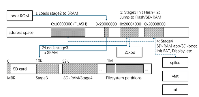
Thumb instructions are between 2 and 4 bytes, this has at least 130 129128 instructions, therefore it will not be smaller than 260 256 bytes.
Edit: Actually I miscounted, it seems to be exactly 128 instructions, so potentially 256 bytes. But this makes me suspicious that it’s just a direct copy of the existing code.
Edit2: The cortex m0+ manual says bl is a 4 byte instruction, so this is probably bigger than 256 bytes.

thanks for checking out. guess I’ll just compile and objdump it to find out!

update: after a few rounds of back and forth it ends up with a valid assembly program, but size=0x174

update: after a few more rounds, forcing it to reuse registers and shift for large immediates, it produces the following code, .text size=0xfc:

// ----------------------------------------------------------------------------
// Ultra-minimal SD boot2 - reads 8K (16 sectors)
// ----------------------------------------------------------------------------

#include "pico/asm_helper.S"
pico_default_asm_setup
.section .text

regular_func _stage2_boot
    // Reset SPI0 only
    ldr r0, =0x4000c000
    ldr r1, [r0]
    movs r2, #32
    bics r1, r2
    str r1, [r0]
1:  ldr r1, [r0, #8]
    tst r1, r2
    beq 1b

    // GPIO setup
    ldr r3, =0x40014080
    movs r1, #5
    str r1, [r3]
    str r1, [r3, #8]
    str r1, [r3, #16]
    str r1, [r3, #24]
    
    // GPIO17 output
    ldr r0, =0xd0000000
    movs r2, #2
    lsls r2, #16         // 0x20000
    str r2, [r0, #36]
    str r2, [r0, #20]

    // SPI0 setup
    ldr r0, =0x4003c000
    movs r1, #0
    str r1, [r0, #4]
    movs r1, #250
    str r1, [r0, #16]
    movs r1, #7
    str r1, [r0]
    movs r1, #2  
    str r1, [r0, #4]

    // Init clocks
    movs r3, #6
2:  movs r1, #255
    bl tx
    subs r3, #1
    bne 2b

    // CS low
    ldr r1, =0xd0000000
    str r2, [r1, #24]

    // CMD0
    movs r1, #64
    bl tx
    movs r1, #0
    bl tx
    bl tx
    bl tx  
    bl tx
    movs r1, #149
    bl tx
    bl wait

    // Read multiple sectors starting at block 16
    ldr r0, =0x20010000  // Load address
    movs r4, #16         // Sector count (8K)
    movs r5, #16         // Starting block

read_sector:
    // CMD17 with current block number
    movs r1, #81
    bl tx
    movs r1, #0
    bl tx
    bl tx
    mov r1, r5           // Block number  
    bl tx
    movs r1, #0
    bl tx
    movs r1, #255
    bl tx
    bl wait

    // Wait for data token
3:  bl rx
    cmp r1, #254
    bne 3b

    // Read 512 bytes
    movs r3, #0
    movs r6, #2          // 512 = 2 << 8
    lsls r6, #8
4:  bl rx
    strb r1, [r0, r3]
    adds r3, #1
    cmp r3, r6
    bne 4b

    // Skip CRC (2 bytes)
    bl rx
    bl rx

    // Next sector
    adds r0, r6          // Advance pointer by 512
    adds r5, #1          // Next block
    subs r4, #1          // Decrement sector count
    bne read_sector

    // CS high & jump
    ldr r0, =0xd0000000
    str r2, [r0, #20]
    ldr r0, =0x20010000
    bx r0

// Functions
tx: ldr r0, =0x4003c000
    str r1, [r0, #8]
5:  ldr r0, [r0, #12]
    lsls r0, #27
    bmi 5b
    bx lr

rx: movs r1, #255
    b tx

wait: movs r3, #4
6:  bl rx
    cmp r1, #255
    bne 7f
    subs r3, #1
    bne 6b
7:  bx lr

.end

The pico sdk will do a size check and block stage2 with invalid large size. This one compiles.
Note: this won’t work though – it’s messing up the constants. I need to check the manual.

update: working my way through – I’m getting hang of THUMB and I can see there are a few spots where we can squeeze more (AI does a bad job for reg allocation)