R-01 RISC-V Baremetal with RT-Thread. LCD work, USB in progress

Hi all,

I successfully build and ran RT-Thread (a small embedded OS) on the Devterm R-01 and uConsole R-01 (thanks for @jusentari).

@jusentari made uConsole display work in RTT (experimental parameters, use with caution).

Honestly, R-01 RISC-V core Allwinner D1H is really pain - documentation very limited regarding peripherals, there are no examples and no standalone libraries.
However, if you enjoy brainteasers and some low-level stuff, you’re welcome.
The intention was to make an RT-Thread portable terminal with a working display and keyboard.

I manage to:

  • Create a working LCD MIPI DSI Display driver with a frame buffer.
  • Make some progress on a USB keyboard driver.
  • Boot from SD card and communicate via UART
  • Debugging with GDB

Please note: The battery charging/discharging controller is not yet configured in the driver, so I’m unsure how it affects the battery. I suggest not using the battery with RT-Thread and powering it via USB instead.

Should say: it’s not truly low-level bare-metal from ground as RT-Thread operates with threads and events and the HAL level is quite complex. But it is easier to manage compared to working within the Linux kernel - at least for me, as I’m not an expert in Linux. RT-Thread has great potential, as it supports many packages for GUI, audio, Ethernet, and more.

The code is available at: GitHub - ylyamin/RT-Thread-on-Allwinner-D1H: Experimentation with the RT-Thread Operating System with the Allwinner D1H

Ready images for SD card:

I’m writing a series of articles covering the knowledge and experience I’ve gained:

Finally, I dare to ask for help from the community, please:

I’m really stuck with the USB driver. It can detect device connections, but communication has not started. Perhaps someone would enjoy diving deep into the USB driver to solve this riddle. Ready for issue reports and pull requests.

Picture of LCD Display test in RT-Thread running on uConsole R-01 (by @jusentari):

Picture of LCD Display test in RT-Thread running on Devterm R-01:

3 Likes

I have a uConsole and tried the uConsole image. It does boot into RT-Thread and the backlight comes on, but typing in “lcd_draw_point 100 100” doesn’t show anything on the screen. Here is the output from UART: https://pastebin.com/rsA4SrAK
I’ll be troubleshooting, but hopefully it’s just a screen config fix. Thank you so much for all your work on this though, it’s a huge cache of information!!

1 Like

Hi @jusentari
Thank you very much. I glad that someone appreciated my work, so it wasn’t in vain)
I believe I found issue:
Changed file rt-thread/bsp/allwinner/libraries/drivers/drv_i2c.c

-#ifdef BSP_USING_CWP_DT_R01
+#if defined BSP_USING_CWP_DT_R01 || defined BSP_USING_CWP_UC_R01

Please try new image RT-Thread-on-Allwinner-D1H/image/sd_image_uconsole.img at master · ylyamin/RT-Thread-on-Allwinner-D1H · GitHub

1 Like

Unfortunately that image also didn’t work with “lcd_draw_point 100 100”, although I did see that the boot output did change: uConsole UART Output 2 - Pastebin.com
Hopefully I’ll have some more time this evening to dig in to the code. I really appreciate the fix as well, thank you.

1 Like

Thanks for your support

Yes without a device is hard for me to figure out.
Only should say - when you have time maybe you can try if possible please:

  1. Change debug level in file rt-thread\bsp\allwinner\libraries\libos\include\log.h
-#define DBG_LVL DBG_ERROR
+#define DBG_LVL DBG_INFO
  1. Play with what time will be power provided by func _axp_LCD_control(1) and reset will be called by panel_rst(1).
    Maybe need to change the sequence order somehow in file:
    rt-thread/bsp/allwinner/libraries/sunxi-hal/hal/source/disp2/disp/lcd/cwu50.c
static s32 LCD_open_flow(u32 sel)
{
    LCD_OPEN_FUNC(sel, LCD_power_on, 100);	 //open lcd power, and delay 50ms
    LCD_OPEN_FUNC(sel, LCD_panel_init, 200);  //open lcd power, than delay 200ms

static void LCD_power_on(u32 sel)
{
	_axp_LCD_control(0);    //power off
	sunxi_lcd_delay_us(200);
	_axp_LCD_control(1);    //power on
	
static void LCD_panel_init(u32 sel)
{
    u32 i;
    printk("<0>raoyiming +++ LCD_panel_init\n");
	
    /**/
    panel_rst(1);
    sunxi_lcd_delay_ms(10);
    
	panel_rst(0);
    sunxi_lcd_delay_ms(50);
    
	panel_rst(1);
    sunxi_lcd_delay_ms(200);

According to the display datasheet https://github.com/clockworkpi/uConsole/blob/master/JD9365DA-H3_DS_V0.01_20200819.pdf:

Maybe order should be like this:

static s32 LCD_open_flow(u32 sel)
{
    //LCD_OPEN_FUNC(sel, LCD_power_on, 100);
    LCD_OPEN_FUNC(sel, LCD_panel_init, 200);

static void LCD_panel_init(u32 sel)
{
    _axp_LCD_control(0);
    sunxi_lcd_delay_ms(100);

    /*start*/
    panel_rst(1);
    _axp_LCD_control(1);

    /*RPWIRES*/
    sunxi_lcd_delay_ms(10);
    panel_rst(0);

    /*tRESETH*/
    sunxi_lcd_delay_ms(10);
	
   /*init sequence*/

I’m not sure but seems when panel_rst(1) then voltage is low and when panel_rst(0) is high.

  1. Can check voltage in power module by commands:
msh /> axp_get_enable
msh /> axp_get_voltage
1 Like

Thanks again for the help! I’ve been testing out a ton of different fixes based on your input, but haven’t made a breakthrough. I built RTT and got it running on my uConsole, but the screen still didn’t respond to the draw command. I don’t see anything strange in the verbose log either: uConsole Init 3 - Pastebin.com
I ran those commands you suggested and those look how I would expect:

msh />axp_get_enable 
Reg name:'DCDC1-5 ALDO1-2 DC5LDO Control' addr: 10 value: 8b
    ALDO2_Enable 1
    ALDO1_Enable 0
    DCDC5_Enable 0
    DCDC4_Enable 0
    DCDC3_Enable 1
    DCDC2_Enable 0
    DCDC1_Enable 1
    DC5LD_Enable 1
Reg name:'ELDO1-3 DLDO1-4 DC1SW Control ' addr: 12 value: 0
    DC1SW_Enable 0
    DLDO4_Enable 0
    DLDO3_Enable 0
    DLDO2_Enable 0
    DLDO1_Enable 0
    ELDO3_Enable 0
    ELDO2_Enable 0
    ELDO1_Enable 0
Reg name:'ADLDO3 Control                ' addr: 13 value: 1
    ALDO3_Enable 0

DCDC3 & ALDO2 are both enabled here, which is expected for the screen to work.

msh />axp_get_voltage
Reg name:'DLDO1  Voltage Set' addr: 15 value: 26
Reg name:'DLDO2  Voltage Set' addr: 16 value: 0
Reg name:'DLDO3  Voltage Set' addr: 17 value: 0
Reg name:'DLDO4  Voltage Set' addr: 18 value: 0
Reg name:'ELDO1  Voltage Set' addr: 19 value: 26
Reg name:'ELDO2  Voltage Set' addr: 1a value: 0
Reg name:'ELDO3  Voltage Set' addr: 1b value: 0
Reg name:'DC5LDO Voltage Set' addr: 1c value: 3
Reg name:'DCDC1  Voltage Set' addr: 21 value: 17
Reg name:'DCDC2  Voltage Set' addr: 22 value: 20
Reg name:'DCDC3  Voltage Set' addr: 23 value: 60
Reg name:'DCDC4  Voltage Set' addr: 24 value: 45
Reg name:'DCDC5  Voltage Set' addr: 25 value: 10
Reg name:'ALDO1  Voltage Set' addr: 28 value: 26
Reg name:'ALDO2  Voltage Set' addr: 29 value: 26
Reg name:'ALDO3  Voltage Set' addr: 2a value: 11

I checked the voltages and those also look good:
ALDO2 is .7V + (26 * .1V) → 3.3V (VCC)
DCDC3 is .6V + (60 *.02V) → 1.8V (IOVCC)
The formulas come from the AXP228 datasheet (pg. 29 & 33).

However, I have noticed that the screen slowly flickers now that the AXP chip is supplying power to the screen:
output

After testing a ton of initialization sequences, I found that the screen only flickers if all three of these are run:

  1. The LCD screen is powered (_axp_LCD_control(1))
  2. The DSI clock is enabled (sunxi_lcd_dsi_clk_enable(sel))
  3. The cwu50 init sequence is used (using the lcd_init_setting from the cwd686 doesn’t cause flickering)
    This leads me to believe that it’s something specific to the init sequence that is causing an issue. I’m using the init sequence verbatim from the Clockwork patch, so it’s likely some other piece that is incompatible.

I’ve also tried every permutation of enabling/disabling the reset pin ( panel_rst(0)/panel_rst(1)) and powering on/off the panel ( _axp_LCD_control(0)/ _axp_LCD_control(1)), although the sequence you posted seems like the most promising.

As a sanity check, I did load up linux on the included SD card and the screen still worked.

I took a diff between the cwu50 and cwd686 drivers from the Clockwork patch and the only difference was the startup sequence. I also took a diff of the dts files for uc-board & dt-board and the &lcd0 definitions were different of course, but uc-board had spi1 disabled while dt-board did not. I don’t know if that’s much to go off of, but that could be a lead.

At this point I think there is either some implementation detail I’m missing between the cwd686 & cwu50 screens or I need to disable the SPI pins mentioned in the uc-board.dts file. Definitely open to ideas though if there’s anything you can think of.

Hi @jusentari ,

I very appreciate your efforts and still being with me on this.
Yes also didn’t see any wrong in your log and axp commands out. About SPI - did’t think is can affect screen as I can imagine. Maybe I’m wrong but my instinct tells me that the answer is somewhere in the exact timing between the power on / reset / init sequence / clock.
I do some experiments that do not help much, but anyway:

  1. I did a little studying about the voltage on LCD RESET pin (PD19 in D1H). Compiled RTT without LCD driver but with some support functions.
void pd19_init(void)
{
    hal_gpio_set_pull(GPIO_PD19, GPIO_PULL_DOWN);
    hal_gpio_set_driving_level(GPIO_PD19, GPIO_DRIVING_LEVEL3);
    hal_gpio_set_direction(GPIO_PD19, GPIO_DIRECTION_OUTPUT);
}
MSH_CMD_EXPORT_ALIAS(pd19_init, pd19_init, pd19_init);

void pd19_on(void)
{
    hal_gpio_set_data(GPIO_PD19, GPIO_DATA_HIGH);
}
MSH_CMD_EXPORT_ALIAS(pd19_on, pd19_on, pd19_on);

void pd19_off(void)
{
    hal_gpio_set_data(GPIO_PD19, GPIO_DATA_LOW);
}
MSH_CMD_EXPORT_ALIAS(pd19_off, pd19_off, pd19_off);

Then tried to poke the multimeter probe into the connector J302 pin 24, and this what I see:

Command PD19 Voltage
axp_LCD_control_cmd 1 1.4 V
pd19_init 0 V
pd19_on 3.3 V
pd19_off 0 V

Surprisingly, looks like LCD RESET pin is not related to DCDC3 1.8V, is just controlled by D1H. I am not an expert in electronic circuits maybe someone can help with is. Just can’t understand how GPIO can generate 3.3V if its in PULL_DOWN, I expect that it will short it to ground.

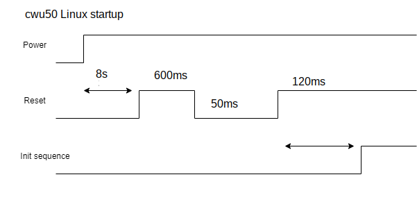
  1. I draw power sequence diagrams as I understood based on code. Strange but it doesn’t correlate with the datasheet:

  2. Only what I can suggest now. Is try to add to cwu50.c proper power off first as shown in the datasheet, then Power On sequence also with datasheet timing.


I also found that sunxi_lcd_pin_cfg(sel, 1) should be called first, without it Devterm display not started

static void LCD_panel_init(u32 sel)
{
    u32 I;
    sunxi_lcd_pin_cfg(sel, 1);

	/*Power off*/
	panel_rst(0);
	sunxi_lcd_delay_ms(120);
    _axp_LCD_control(0);
    sunxi_lcd_delay_ms(100);

	/*power on*/
    _axp_LCD_control(1);

    /*tRPWIRES*/
    sunxi_lcd_delay_ms(10);

    /*tRESETH*/
	panel_rst(1);
    sunxi_lcd_delay_ms(5);

    /*init sequence*/
	for (i = 0; ; i++) {

In the coming days, I will try to compile a Linux kernel with LCD driver.
Will try to measure the voltage on the RESET pin and change timeouts in the driver. Maybe this will give me a hint.
Ideally, it would be great if there was a person with an Logic Analyzer or Oscilloscope (that I don’t have) who can capture power/reset/clock pins due Linux driver init.

1 Like

Going to start off with this image:

It worked!! I’m ecstatic that it’s finally working after so long!
I fixed it by upping the lcd_dclk_freq in the cwu50_config.c file from 62 to 67. There was some trial and error (the flickering gets worse as the number goes up until about 67) but now the screen displays the drawn pixels correctly.
I had tested the initialization timings for the display by touching to pins 24 (LCD RST) and 39 (3.3V) on the J302 connector and this is what mine came out to:

I edited the RTT driver to match but that didn’t help. I then tried to match up some properties that were difference between the cwu50 and the cwd686, like the pixel clock. When I set the cwu50 pixel clock (lcd_dclk_freq) to 55 to match the cwd686, the flickering went away, which was a good sign. I then took a look at the datasheet for the cwu50 and saw this, which matches the resolution of the screen:

(pg. 202)
Plugging the values from the cwu50 config into the formula at the bottom does equal about 62 MHz, which is what the cwu50’s config is set to, but I pushed it further to see if I could increase the bandwidth. That worked! I don’t know if it affects battery life or the life of the screen, but at least there’s something on the screen now.

Also, I checked the schematics for the R01/Main board and SPI1 is just routed to the EXT mPCI port, so it definitely doesn’t have anything to do with the display.

2 Likes

Amazing !
Congratulations @jusentari, yes D1 is pain and gain.
Thank you for your enthusiasm, great work, great is finally run.

Startup sequence 8 sec? Oh is long, I don’t know maybe it could be shorter?

About it is safe to change lcd_dclk_freq from 62 to 67 MHz for uConsole display ?
Need some expert input. I don’t know who knows this stuff, sorry @guu seems you build Linux kernel maybe - you can target us who can advice about frequency, please ?

Cool, @jusentari would be a pleasure if you could do a pull request to repo or just send me the files that you changed, please. I will push it to repo.
And could I put your uConsole green square photo and explanation in the docs If you don’t mind?

1 Like

Yeah, you can put the photo in the docs. I’ll get a PR up with the pixel clock change as well.

1 Like

Great, thank you very much!

(So that everyone knows: we discussed due PR with @jusentari that the driver now works with default power sequence timing, the only change is display freq to 67.)

OK

send email to help@clockworkpi.com with the question

and you are right ,I may build the kernel,but I don’t know much about kernel develoment actually

2 Likes

I’m totally new to this but willing to help.

in CherryUSB doc( CherryUSB/docs/source/porting_usbip.rst at cherryusb-v1.4.0 · cherry-embedded/CherryUSB · GitHub ):

“At the same time, since EHCI is only a host controller and supports only high-speed operation, it is usually paired with an OTG controller and a low/full-speed compatible control unit. The speed is typically retrieved from the OTG registers, so the user needs to implement the usbh_get_port_speed function.”

seems like implement usbh_get_port_speed is enough?
also another piece of porting CherryUSB for WCH CH582(in chinese)

1 Like

nuttx usb driver for pinephone

1 Like

Hi @zoenggit ,

Thank you for your involvement.

  1. Yes you absolutely right:

    According https://wiki.osdev.org/Enhanced_Host_Controller_Interface
    “The Enhanced Host Controller Interface (EHCI) is the single method of interfacing with USB 2.0”

    "On a PC you will normally find the EHCI USB controller on the PCI bus - in fact it is the only access method specified in the specification. USB 2.0 supports interfacing with USB 1.0 devices. However, EHCI is NOT expected to support them. Instead, you will find an UHCI or OHCI companion controller. "

    EHCI and OHCI is low level controllers for High and Full speed USB devices accordantly. Device can be routed to EHCI or OHCI depend what speed of device is.

    And actually I was port CherryUSB already in folder rt-thread/bsp/allwinner/d1s_d1h/packages/CherryUSB/.
    Cherry USB switch from EHCI to OHCI companion controller when I connect USB device but in Cherry USB - OHCI transfer functions is not implemented.

    Because of that I switch to TinyUSB in folder rt-thread/bsp/allwinner/d1s_d1h/packages/TinyUSB/

    However, it did not reach the point when OHCI started to work in TinyUSB.
    More info at - D1-6. USB Keyboard
  1. About PinePhone, yes I also saw this, thank you.
    What scared me in this article was that is ARM and A64 SoC where them port NXP USB driver. But this is a good reason to re-read the article, maybe something new will be revealed

Thanks for clarification. I still have some questions about CherryUSB.

        elseif("${CONFIG_CHERRYUSB_HOST_HCD}" STREQUAL "musb_sunxi")
        list(APPEND cherryusb_srcs ${CMAKE_CURRENT_LIST_DIR}/port/musb/usb_hc_musb.c)
        list(APPEND cherryusb_srcs ${CMAKE_CURRENT_LIST_DIR}/port/musb/usb_glue_sunxi.c)

Seems like usb_hc_ehci.c shouldn’t be compiled for allwinner chips. for f1c100s:

#define PKG_USING_CHERRYUSB
#define PKG_CHERRYUSB_DEVICE
#define PKG_CHERRYUSB_DEVICE_FS
#define PKG_CHERRYUSB_DEVICE_MUSB
#define PKG_CHERRYUSB_DEVICE_MUSB_SUNXI
#define PKG_CHERRYUSB_DEVICE_CDC
#define PKG_CHERRYUSB_DEVICE_CDC_TEMPLATE
#define PKG_CHERRYUSB_HOST
#define PKG_CHERRYUSB_HOST_MUSB
#define PKG_CHERRYUSB_HOST_MUSB_SUNXI
#define PKG_CHERRYUSB_HOST_CDC
#define PKG_CHERRYUSB_HOST_HID
#define PKG_CHERRYUSB_HOST_MSC
#define PKG_CHERRYUSB_HOST_TEMPLATE
#define PKG_USING_CHERRYUSB_LATEST_VERSION

@zoenggit I am not sure.

In my project, I change build scripts to support this.
rt-thread/bsp/allwinner/d1s_d1h/.config:

CONFIG_PKG_CHERRYUSB_HOST=y
CONFIG_PKG_CHERRYUSB_HOST_EHCI_CUSTOM=y

rt-thread/bsp/allwinner/d1s_d1h/packages/CherryUSB/SConscript:

 if GetDepend(['PKG_CHERRYUSB_HOST_EHCI_CUSTOM']):
        path += [cwd + '/port/ehci']
        path += [cwd + '/port/ohci']
        src += Glob('port/ehci/usb_hc_ehci.c')
        src += Glob('port/ohci/usb_hc_ohci.c')

I am not sure either. Maybe musb is for OTG capable port only.

@zoenggit Ah, sorry, I misunderstood the question.
No, I believe EHCI/OHCI should be used, as EHCI/OHCI registers are present in AW D1H documentation and initialisation is present in RTT sunxi-hal.

Thanks. So CherryUSB is no go.

As for tinyusb, this issue seems similar:
hathach/tinyusb/discussions/1599 (from github, complete URL seems trigger spam filter)

I thought that EHCI will be trouble on its own. So I switched to OHCI as more easier thing to get going. I switched to OHCI driver from pull request from @Ryzee119, added few places to clear/invalidate caches and … works :slight_smile: