Like many others I was a little frustrated with the reliability of my trackball. Even after cleaning it a couple of times. Instead of swapping the ball I decided to try to install a Glidepoint trackpad from Cirque (available through Mouser) that I had lying around. So far I am pretty happy with the result.
The trackpad is very low profile, the surface is still a little less than 1 mm below the top of the buttons. I will probably add a new cover that is going to increase the thicknes a little. The original cover the board came with got damaged when I desoldered the connector on the back but I have noticed that my finger does not slide quite as well on the bare PCB. I am also not sure about the look of the exposed silkscreen.
Very thin 30 AWG wires are routed through the hole for the trackball and another one I had to drill into the center frame of the uConsole right next to the display cable. The trackpad is then connected using I2C to an Adafruit QT Py RP2040. QMK supports the RP2040 and apparently also has some support for these trackpads but for now I am just using Circuitpython example code from 2bndy5 on Github.
I had to fiddle a little with the settings of the thing to deal with some yittering but it works pretty well now. The only issue is that it stops working completely if I do not touch the case of the uConsole Probably some EMI-issue since this does not happen when I connect the trackpad to my PC and the uConsole stays off. Not really sure what I could do about this other than using thicker shielded cable.
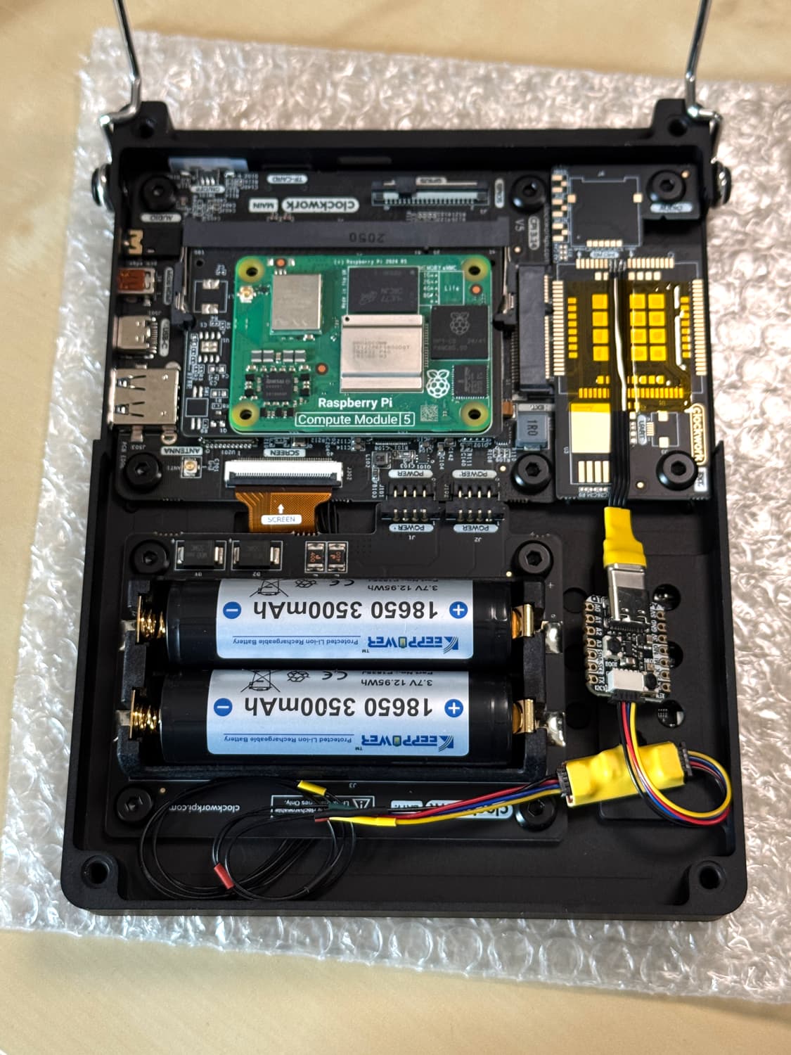
This is the look on the inside. You can see the wires right next to the display cable. The RP2040 board is now covered and insulated. I wanted to leave it exposed for the photo. The second small breakout board is for the I2C pullup resistors.
I tried to get Cirque to sell me the 16 mm variant of the trackpad (not available on Mouser) but they did not respons to my emails… In hindsight the 23 mm variant is probably better anyway. I dont think the tradeoff between range and precision would work out well with the smaller one.
Sorry for the late response, only now saw your message.
I didn’t really do anything new, just assembled bits and pieces from others.
Removing the R1 resistor to configure the trackpad for I2C is described here and my code it basically just the relative mode example by 2bndy5 with all the unnecessary stuff removed.
At first I thought this small hole would be enough:
(second post because of URL and image posting restrictions)
That way there is just enough room for the connector to fit even when the display and keyboard PCB are alread installed. You just have to cut of the small plastic side tabs on the connector.
I used this breakout to add the I2C pullup resistors (10k and 4.7k Ohm should work, I think I used 4.7) and this RP2040 board. Since the RP2040 is simulating a regular USB mouse no configuration of the uConsole is required.
I am still experimenting with different parameters for the trackpad and I think I will add a black cover. After that I might make a printables account and upload the STLs (cannot upload STLs here unfortunately).
Edit: The big ribbon cable connector the trackpad comes with is easy to remove. The plastic housing can be pulled off wit hrelatively little force and after that each pin can be desoldered one by one