Statement Regarding AIO v2 Internal USB-C Power Supply Issue and Compensation Plan

Last week, we were informed that the AC1200 WiFi card was not functioning properly with the AIO V2’s internal USB-C port. Upon investigation, we discovered that the threshold for the internal USB-C current-limiting switch was configured to 0.68A, whereas it should have been set to 1.58A.

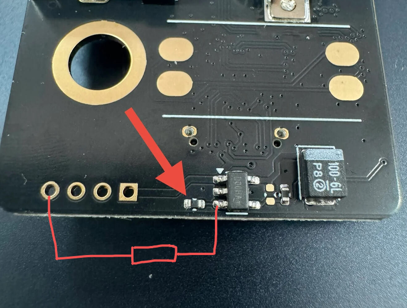
While 0.68A meets the requirements for USB 2.0 (meaning USB 2.0 devices work without issue), it causes insufficient power delivery when using USB 3.0 devices. To resolve this issue, the resistor shown in the image below needs to be replaced with a 4.3kΩ resistor (0402 package size). It doesn’t need to be a 4.3kΩ resistor. The current limit threshold is calculated using the formula: I(limit) = 6.8k/Rset. The maximum current the MT9700 can handle is 2A, so the minimum resistor is 3.4kΩ. So any 0402 package size resistor with a value between 5.6kΩ and 3.4kΩ would work.

Why did this issue occur despite functional testing?

The test script I developed was not fully comprehensive. During the USB test, the script only enabled power to the USB interface and used the lsusb command to verify if a new USB 3.0 device was detected. It did not perform a test of the actual WiFi connection (active data load), which is where the power insufficiency occurs.

Affected Orders: All AIO v2 orders shipped before last Friday (January 16). The RJ45 Ethernet and USB 3.0 expansion board is not involved.

Compensation Plan:

Since we currently have no stock available for direct replacements, the principle behind these compensation and replacement solutions is that you will not incur any additional expenses. Users who retain the product, either repair it themselves or mail it back for repair, will receive a partial refund as a sincere apology.

I plan to manufacture a small batch of the AIO v2. But it depends on our remaining cash flow after this compensation plan is completed. Since we are offering an option for an immediate full refund upon proof of destruction (to save you the wait time for return shipping), we are absorbing the total financial loss on those units. It’s not just about the profit; it includes the money I already spent on manufacturing and shipping. This significantly impacts the funds available for the next batch.

Here are the specific compensation options:

Option 1: Self-Repair and Receive a $20 Refund (This amount is roughly equivalent to the profit I earn from a single unit.). Any damage caused during the repair process will be covered by us. If the PCB is damaged during your attempt, you can send it back for repair, and we will cover all associated shipping costs.

Option 2: Return for Repair and Receive a $10 Refund. We will cover all associated shipping costs.

Option 3: Return for a Full Refund. We will cover all associated shipping costs. We will issue the refund immediately after the carrier picks up the package. Alternatively, if you have lost confidence in us and do not wish to wait for the carrier pickup to receive your refund, you may record a video of yourself destroying the PCB as requested, and we will issue the refund immediately.

If you choose to receive your compensation as a store coupon instead of cash, we will add an extra $5 to the amount. As mentioned earlier, we may not be able to produce and restock the AIO v2 again in the short term. Therefore, if you want to use the coupon code for the AIO v2, you will have to wait for it to restock. But you can switch to cash compensation at any time before redeeming if you don’t want to wait any longer.

How to Apply for Compensation:

Please fill in this Google form: https://forms.gle/XnY1pY4sKFc54fLBA. We process requests submitted the previous day on every business day.

I am deeply grateful to everyone who has spoken up for me on forums and Reddit. Your kindness has been a source of great comfort to me during this difficult time.

However, the fact remains that I delivered a product that did not match what I advertised, and I will not shy away from taking responsibility for that. I am committed to ensuring that you ultimately receive a fully functional product, and I will be providing cash compensation to the affected users as promised.

18 Likes

That’s a very generous offer.

I hope for you that as many customers as possible decide not to seek compensation. I have already made it clear that I consider the problem to be minor. Unfortunately, I was attacked for this via private message.

Everyone makes mistakes sometimes. If this is exploited, no one will want to take risks and bring something new to the community. For your next project, please increase your profit margin so that problems like this can be better absorbed.

Thank you very much for your great work!

11 Likes

I posted somethign similar in Reddit, but thanks for this statement. If I’m brave anough, I’ll attempt to replace the resistor, else, will send it back for repair. Regardless, I’ll not seek compensation since at the end will have a working board (I think of it as a learning event for an add-on that greatly increases the value of the uconsole) .

Thanks for all the time spent designing and building these boards!

4 Likes

Hi. I have a question. There are two of these circuits, one as shown in picture above. The other near the external USB C. Are both limited low?

(And a secondary question: does the power for the other / hole soldered internal USB piggyback on this circuit too?)

((Edit: And third … no, figured this out. :partying_face: ))

1 Like

Thanks for the comprehensive Info. I don’t currently plan to use the internal USB-C port and if the need arises, I’ll be able to change the resistor myself. So in my case there is no need for further support.

3 Likes

I expect this will only be of interest to those in the UK. DM me if interested.

I’ve ordered 100x 0402 4K3 resistors. I’ll need one to repair my board! If anyone would like one then just pay the postage - I’ve got a label printer and plenty of envelopes.

Just to add, I’m not intending to take @vileer up on their kind compensation offer. As someone who occasionally builds/sells hardware and 3D prints. I have an appriciation of the effort which goes on behind the scenes. Keep on building!

3 Likes

I am UK but I think the soldering is beyond my skills.

does this problem also exist in the AIO v1 board?

Interested in knowing if mine is affected.. received it today.. according to my order tracking it was “on its way” the 17th.. but when you go to the tracking site itself it says it was already in transit earlier…

You can give me the order number, and I will double-check it.

No, only V2 that sent out before Jan 15.

1 Like

Only the internal USB-C and the pinheader are effect. The external USB-C have individual current limit switch, but has the right configure resistor.

It did not work as I advertised, so I accepted any kind of the feedback. But I am really sorry that you had to go through this, which you should never have had to experience.

4 Likes

Hiya Vileer,

My order is 5003, and the status is about to be shipped on the 15th Jan, does this mean it is waiting to be shipped and thus the V2.1 reworked edition?:wink: Cheers mate!

There is not kind of V2.1, but yes, your board got fixed.

2 Likes

Vileer, thank you very much for the quick reply!!! I am very happy to hear that! (English is not my first language so i may have not typed correctly, I meant it as a bit of a joke about V2.1!!)

If there is clearance in the case, looks like you could bodge a longer resistor in there. How much distance is between the pad and the pin of that chip? Could you get an 06 or larger in there to make it easier for people to repair?

Getting the 0402 out is easy, big blog of solder on your iron and heat the whole thing until it comes off. A bigger 06 might be able to be easily hand solder, bigger would be easier and potentially even an eighth way could be glued to the board and soldered by hand.

1 Like

You can even just solder a discrete resistor in parallel, as shown below, without removing the 0402 resistor. The final resistance is (10k*R)/(10k+R) . The final resistance should be greater than 3.4K. So the range of the parallel resistor should be between 5.2K and 7.5K.

12 Likes

Just to share…

i just bridged a discrete resistor across the 2 pads as shown.
Used a 5.6K resistor as that is what i had in my box. Didn’t remove the existing SMD resistor. The result is 3.6KOhms. This is perfect as it brings it up to about 1.9A


i did put a shrink wrap around the resistor and some pins to make sure that i can still tap on the USB 2.0 pins if required.

All in all, this works perfect. Definitely do-able at home. No shipping and all that extra stuff. :grin:

thanks to @vileer responding so quickly to my PMs.

10 Likes

this is WAYYYY more doable. how’s the spacing when you assemble it?